| Last Modified: 01-27-2025 | 6.11:8.1.0 | Doc ID: RM100000002Q1CD |
| Model Year Start: 2025 | Model: GR Corolla | Prod Date Range: [09/2024 - ] |
| Title: G16E-GTS (ENGINE MECHANICAL): ENGINE ASSEMBLY: INSTALLATION; 2025 MY GR Corolla [09/2024 - ] | ||
INSTALLATION
CAUTION / NOTICE / HINT
CAUTION:
The engine assembly with transaxle is very heavy. Be sure to follow the procedure described in the repair manual, or the engine lifter may suddenly drop.
NOTICE:
This procedure includes the installation of small-head bolts. Refer to Small-Head Bolts of Basic Repair Hint to identify the small-head bolts.
Click here
![2019 - 2025 MY Corolla Corolla Hatchback Corolla HV GR Corolla [06/2018 - ]; INTRODUCTION: REPAIR INSTRUCTION: PRECAUTION](/t3Portal/stylegraphics/info.gif)
HINT:
Perform "Inspection After Repair" after replacing the engine assembly.
Click here
PROCEDURE
1. INSTALL ENGINE HANGERS
Click here
2. REMOVE ENGINE ASSEMBLY FROM ENGINE STAND
(a) Remove the engine assembly from the engine stand.
3. INSTALL NO. 1 CRANKSHAFT POSITION SENSOR PLATE
Click here
4. INSTALL FLYWHEEL SUB-ASSEMBLY (for Manual Transaxle)
Click here
5. INSTALL COVER AND DISC CLUTCH SET (for Manual Transaxle)
Click here
6. INSTALL MANUAL TRANSAXLE ASSEMBLY (for Manual Transaxle)
Click here
7. INSTALL DRIVE PLATE AND RING GEAR SUB-ASSEMBLY (for Automatic Transaxle)
Click here
8. INSTALL AUTOMATIC TRANSAXLE ASSEMBLY (for Automatic Transaxle)
Click here
9. INSTALL DRIVE PLATE AND TORQUE CONVERTER CLUTCH SETTING BOLT (for Automatic Transaxle)
Click here
10. INSTALL FRONT SUSPENSION CROSSMEMBER SUB-ASSEMBLY
for Manual Transaxle:
Click here
for Automatic Transaxle:
Click here
11. INSTALL PROPELLER SHAFT HEAT INSULATOR
Click here
12. INSTALL EXHAUST MANIFOLD CONVERTER SUB-ASSEMBLY
Click here
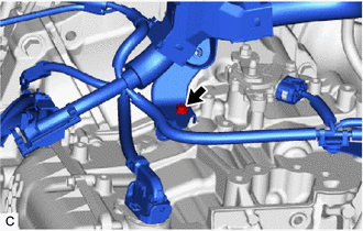
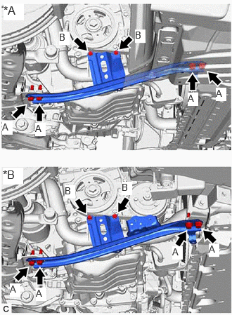
13. INSTALL ENGINE WIRE
(a) Connect all the connectors and clamps, and install the engine wire to the engine assembly with transaxle.
(b) for Manual Transaxle:
|
(1) Install the bolt. Torque: 10 N·m {102 kgf·cm, 7 ft·lbf} |
|
|
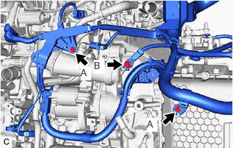
(2) Install the 2 bolts. Torque: 10 N·m {102 kgf·cm, 7 ft·lbf} |
|
|
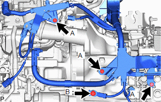
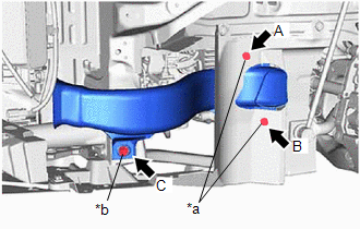
(3) Install the 4 bolts. Torque: Bolt (A) : 10 N·m {102 kgf·cm, 7 ft·lbf} Bolt (B) : 20 N·m {204 kgf·cm, 15 ft·lbf} |
|
|
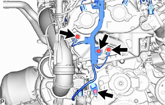
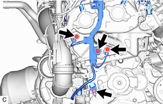
(4) Install the 4 bolts. Torque: 10 N·m {102 kgf·cm, 7 ft·lbf} |
|
(c) for Automatic Transaxle:
|
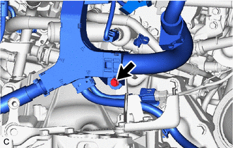
(1) Install the bolt. Torque: 10 N·m {102 kgf·cm, 7 ft·lbf} |
|
|
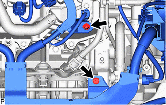
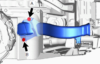
(2) Install the 3 bolts. Torque: Bolt (A) : 10 N·m {102 kgf·cm, 7 ft·lbf} Bolt (B) : 20 N·m {204 kgf·cm, 15 ft·lbf} |
|
|
(3) Install the 2 bolts. Torque: 10 N·m {102 kgf·cm, 7 ft·lbf} |
|
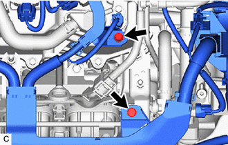
|
(4) Install the 4 bolts. Torque: 10 N·m {102 kgf·cm, 7 ft·lbf} |
|
14. INSTALL NO. 4 WATER BY-PASS HOSE (for Automatic Transaxle)
(a) Install the No. 4 water by-pass hose to the engine assembly with transaxle and slide the 2 clips to secure it.
15. INSTALL NO. 5 WATER BY-PASS HOSE (for Automatic Transaxle)
(a) Install the No. 5 water by-pass hose to the engine assembly with transaxle and slide the 2 clips to secure it.
(b) Engage the clamp
16. INSTALL GENERATOR ASSEMBLY
Click here
17. INSTALL TIMING GEAR COVER INSULATOR
(a) Install the timing gear cover insulator to the cylinder block sub-assembly.
18. INSTALL V-RIBBED BELT TENSIONER ASSEMBLY
(a) Install the V-ribbed belt tensioner assembly with the 2 bolts.
Torque:
21 N·m {214 kgf·cm, 15 ft·lbf}
19. INSTALL FAN AND GENERATOR V BELT
Click here
20. INSTALL FLYWHEEL HOUSING UNDER COVER
|
(a) Align the claw of the flywheel housing under cover with the notch of the cylinder block sub-assembly then install. NOTICE: Make sure that the orientation is correct when installing. |
|

21. INSTALL STARTER ASSEMBLY
Click here
22. CONNECT ENGINE WIRE (for Automatic Transaxle)
Click here
23. CONNECT TRANSMISSION OIL COOLER (for Automatic Transaxle)
Click here
24. INSTALL FLYWHEEL HOUSING SIDE COVER
(a) Install the flywheel housing side cover to the cylinder block sub-assembly.
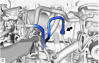
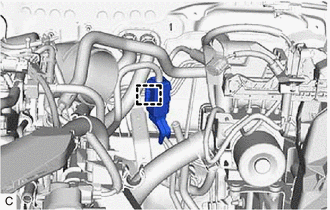
25. INSTALL NO. 1 FUEL VAPOR FEED HOSE
(a) Engage the 2 clamps.
(b) Install the No. 1 fuel vapor feed hose to the purge valve (purge VSV).
26. INSTALL ENGINE MOUNTING INSULATOR SUB-ASSEMBLY RH
HINT:
Perform this procedure only when replacement of the engine mounting insulator sub-assembly RH is necessary.
|
(a) Temporarily install the engine mounting insulator sub-assembly RH to the vehicle. |
|
(b) Install the 2 bolts and nut in the order shown in the illustration.
Torque:
72 N·m {734 kgf·cm, 53 ft·lbf}
|
(c) Connect the air conditioner tube with the clamp. |
|
27. INSTALL RESERVE TANK ASSEMBLY
HINT:
Perform this procedure only when replacement of the reserve tank assembly is necessary.
(a) Install the bolt and reserve tank assembly to the vehicle.
Torque:
5.0 N·m {51 kgf·cm, 44 in·lbf}
(b) Connect the No. 3 water by-pass hose to the reserve tank assembly and slide the clip to secure it.
28. INSTALL ENGINE MOUNTING INSULATOR LH
HINT:
Perform this procedure only when replacement of the engine mounting insulator LH is necessary.
|
(a) Temporarily install the engine mounting insulator LH to the vehicle. |
|
(b) Install the 4 bolts and nut in the order shown in the illustration.
Torque:
42 N·m {428 kgf·cm, 31 ft·lbf}
|
(c) Engage the clamp. |
|
29. REMOVE ENGINE HANGERS
Click here
30. INSTALL FLEXIBLE HOSE BRACKET (for Automatic Transaxle)
Click here
31. INSTALL ENGINE MOUNTING BRACKET CAP
(a) Install the engine mounting bracket cap to the engine mounting bracket RH.
32. INSTALL ENGINE ASSEMBLY WITH TRANSAXLE
(a) Using height adjustment attachments and plate lift attachments to keep the engine assembly with transaxle and front suspension crossmember sub-assembly level, set an engine lifter underneath the engine assembly with transaxle and front suspension crossmember sub-assembly.
NOTICE:
- Using height adjustment attachments and plate lift attachments, keep the engine assembly with transaxle horizontal.
- Do not perform any procedures while the engine assembly is suspended because doing so may cause the engine assembly to drop, resulting in injury. However, the engine assembly needs to be suspended when it is installed to or removed from an engine stand.
- To prevent the No. 2 oil pan sub-assembly from deforming, do not place any attachments under the No. 2 oil pan sub-assembly of the engine assembly with transaxle.
(b) Operate the engine lifter and install the engine assembly with transaxle to the vehicle.
CAUTION:
Do not raise the engine assembly with transaxle more than necessary. If the engine is raised excessively, the vehicle may also be lifted up.
NOTICE:
- Make sure that the engine assembly with transaxle is clear of all wiring and hoses.
- While raising the engine assembly with transaxle into the vehicle, do not allow it to contact the vehicle.
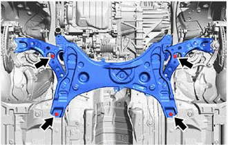
|
(c) Connect the front suspension crossmember sub-assembly to the vehicle with the 4 bolts. Torque: 141 N·m {1438 kgf·cm, 104 ft·lbf} |
|
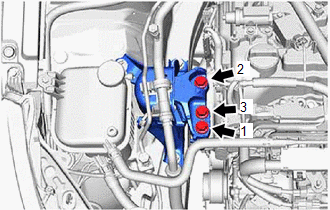
|
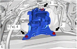
(d) Install the engine mounting insulator sub-assembly RH to the engine mounting bracket RH with the 3 bolts in the order shown illustration. Torque: 72 N·m {734 kgf·cm, 53 ft·lbf} |
|
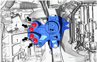
|
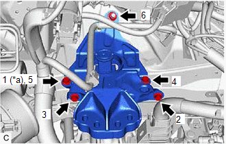
(e) Install the engine mounting insulator LH to the transaxle assembly with the 4 bolts in the order shown illustration. Torque: 65 N·m {663 kgf·cm, 48 ft·lbf} |
|
33. CONNECT NO. 1 TRANSMISSION OIL COOLER HOSE ASSEMBLY (for Automatic Transaxle)
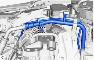
(a) Connect the No. 1 transmission oil cooler hose assembly and slide the 2 clips to secure it.
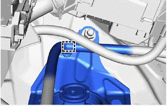
(b) Engage the clamp.
34. CONNECT NO. 1 CLUTCH HOSE (for Manual Transaxle)
|
(a) Connect the No. 1 clutch hose to the clutch flexible hose bracket with a new clip. |
|
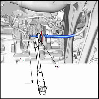
(b) Using a 10 mm union nut wrench, connect the bleeder clutch release tube to the No. 1 clutch hose.
Torque:
Specified tightening torque :
15.2 N·m {155 kgf·cm, 11 ft·lbf}
HINT:
-
Calculate the torque wrench reading when changing the fulcrum length of the torque wrench.
Click here
- When using a 10 mm union nut wrench (fulcrum length of 22 mm (0.866 in.)) + torque wrench (fulcrum length of 162 mm (6.38 in.)): 13.4 N*m (137 kgf*cm, 10 ft.*lbf)
35. INSTALL NO. 1 AIR TUBE
(a) Tighten the 2 hose clamps to install the No. 1 air tube.
Torque:
6.0 N·m {61 kgf·cm, 53 in·lbf}
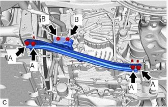
36. INSTALL REAR SIDE RAIL REINFORCEMENT SUB-ASSEMBLY RH
|
(a) Install the rear side rail reinforcement sub-assembly RH to the front suspension crossmember sub-assembly and vehicle body with the 6 bolts. Torque: Bolt (A) : 70 N·m {714 kgf·cm, 52 ft·lbf} Bolt (B) : 7.0 N·m {71 kgf·cm, 62 in·lbf} |
|
37. INSTALL REAR SIDE RAIL REINFORCEMENT SUB-ASSEMBLY LH
|
(a) for Manual Transaxle: (1) Install the rear side rail reinforcement sub-assembly LH to the front suspension crossmember sub-assembly and vehicle body with the 4 bolts. Torque: 70 N·m {714 kgf·cm, 52 ft·lbf} |
|
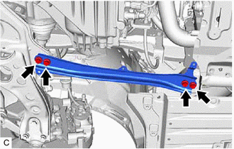
|
(b) for Automatic Transaxle: (1) Install the rear side rail reinforcement sub-assembly LH to the front suspension crossmember sub-assembly and vehicle body with the 6 bolts. Torque: Bolt (A) : 70 N·m {714 kgf·cm, 52 ft·lbf} Bolt (B) : 8.3 N·m {85 kgf·cm, 73 in·lbf} |
|
38. FRONT DRIVE SHAFT ASSEMBLY DRIVE SHAFT ASSEMBLY
Click here
39. INSTALL PROPELLER WITH CENTER BEARING SHAFT ASSEMBLY
Click here
40. CONNECT NO. 2 STEERING INTERMEDIATE SHAFT ASSEMBLY
Click here
41. INSTALL COLUMN HOLE COVER SILENCER SHEET
Click here
42. CONNECT DISCHARGE HOSE SUB-ASSEMBLY
Click here
43. CONNECT SUCTION HOSE SUB-ASSEMBLY
Click here
44. CONNECT FUEL TUBE SUB-ASSEMBLY
|
(a) Connect the fuel tube sub-assembly to the fuel pipe.
Click here
|
|
|
(b) Install the No. 1 fuel pipe clamp to the fuel tube sub-assembly. |
|
45. CONNECT INLET HEATER WATER HOSE
(a) Connect the inlet heater water hose to the No. 1 water by-pass pipe and slide the clip to secure it.
46. CONNECT OUTLET HEATER WATER HOSE
(a) Connect the outlet heater water hose to the No. 3 water by-pass pipe and slide the clip to secure it.
47. CONNECT NO. 1 FUEL VAPOR FEED HOSE
(a) Connect the No. 1 fuel vapor feed hose to the fuel tank to canister tube.
48. CONNECT NO. 2 WATER BY-PASS HOSE
(a) Connect the No. 2 water by-pass hose to the No. 4 water by-pass pipe and slide the clip to secure it.
49. CONNECT NO. 1 WATER BY-PASS HOSE
(a) Connect the No. 1 water by-pass hose to the No. 4 water by-pass pipe and slide the clip to secure it.
50. CONNECT CHECK VALVE UNION TO CONNECTOR TUBE HOSE
Click here
51. CONNECT TRANSMISSION CONTROL CABLE ASSEMBLY
(a) for Manual Transaxle:
|
(1) Connect the transmission control cable assembly to the control cable bracket assembly with 2 new clips (B). NOTICE: Make sure that the paint marks on the transmission control cable assembly are aligned with the slits in the control cable bracket assembly before installing the clips. |
|
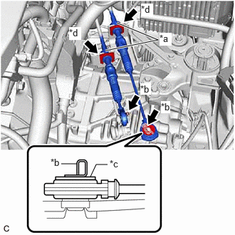
(2) Connect the transmission control cable assembly to the manual transaxle assembly with the 2 clips (A).
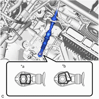
(b) for Automatic Transaxle:
(1) Connect the transmission control cable assembly to the No. 1 transmission control cable bracket with a new clip.
|
(2) Connect the transmission control cable assembly to the transmission control shaft lever as shown in the illustration. |
|
52. INSTALL ECM
Click here
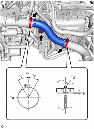
53. INSTALL NO. 5 AIR HOSE
|
(a) Install the a new No. 5 air hose to the air tube assembly and tighten the hose clamp. Torque: 6.0 N·m {61 kgf·cm, 53 in·lbf} |
|
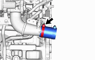
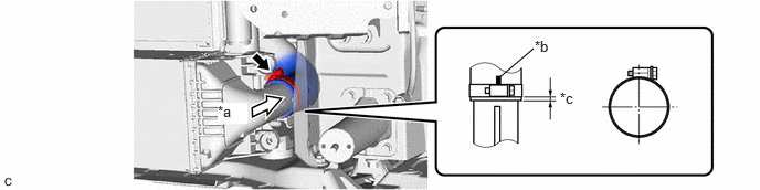
54. INSTALL NO. 4 AIR HOSE
(a) Install the a new No. 4 air hose to the intercooler tighten the hose clamp.
|
*a |
View A |
*b |
Paint Mark |
|
*c |
3 to 6 mm (0.1181 to 0.2362 in.) |
- |
- |
Torque:
6.0 N·m {61 kgf·cm, 53 in·lbf}
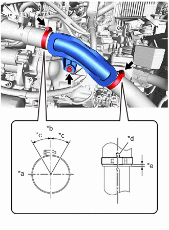
55. INSTALL NO. 2 AIR TUBE
|
(a) for Manual Transaxle: (1) Install the No. 2 air tube with the bolt. Torque: 21 N·m {214 kgf·cm, 15 ft·lbf} (2) Tighten the 2 hose clamps. Torque: 6.0 N·m {61 kgf·cm, 53 in·lbf} |
|
|
(b) for Automatic Transaxle: (1) Install the No. 2 air hose with the bolt. Torque: 43 N·m {438 kgf·cm, 32 ft·lbf} (2) Tighten the 2 hose clamps. Torque: 6.0 N·m {61 kgf·cm, 53 in·lbf} |
|
56. CONNECT NO. 2 RADIATOR HOSE
(a) Connect the No. 2 radiator hose to the water inlet with thermostat sub-assembly and slide the clip to secure it.
57. CONNECT NO. 1 RADIATOR HOSE
(a) Connect the No. 1 radiator hose to the water outlet and slide the clip to secure it.
58. CONNECT ENGINE WIRE
(a) Engage the clamp to connect the engine wire to the vehicle.
(b) Engage the 2 clamps to connect the engine wire to the vehicle.
(c) Connect the engine wire to the vehicle with the 2 bolts.
Torque:
10 N·m {102 kgf·cm, 7 ft·lbf}
(d) Connect the 3 connectors to the engine room relay block.
(e) Install the nut.
Torque:
10 N·m {102 kgf·cm, 7 ft·lbf}
(f) Install the nut.
Torque:
7.6 N·m {77 kgf·cm, 67 in·lbf}
59. INSTALL COVER RELAY BLOCK UPR
(a) Install the junktion block cover.
60. INSTALL NO. 1 RELAY BLOCK COVER
(a) Install the No. 1 relay block cover.
61. INSTALL AIR CLEANER BRACKET
(a) Install the air cleaner bracket with the 2 bolts.
Torque:
7.0 N·m {71 kgf·cm, 62 in·lbf}
(b) Engage the clamp.
62. INSTALL AIR CLEANER WITH AIR CLEANER HOSE
Click here
63. INSTALL NO. 1 AIR CLEANER INLET
Click here
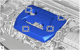
64. INSTALL NO. 1 ENGINE COVER SUB-ASSEMBLY
|
(a) Engage the 4 clamps to install the No. 1 engine cover sub-assembly. NOTICE:
|
|
65. CONNECT CABLE TO NEGATIVE BATTERY TERMINAL
Click here
66. INSTALL SPARE WHEEL CUSHION
Click here
67. INSTALL DECK BOARD ASSEMBLY
Click here
68. BLEED CLUTCH LINE (for Manual Transaxle)
Click here
69. ADD ENGINE OIL
Click here
70. ADD ENGINE COOLANT
Click here
71. ADD AUTOMATIC TRANSAXLE FLUID (for Automatic Transaxle)
Click here
72. ADD MANUAL TRANSAXLE OIL (for Manual Transaxle)
Click here
73. INSTALL REAR ENGINE UNDER COVER LH
(a) Install the rear engine under cover LH to the vehicle with the screw and 4 clips.
74. INSTALL REAR ENGINE UNDER COVER RH
(a) Install the rear engine under cover RH to the vehicle with the screw and 4 clips.
75. INSTALL NO. 3 ENGINE UNDER COVER AIR GUIDE
|
(a) Install the No. 3 engine under cover air guide with the bolt and 2 screws. NOTICE: Temporary tighten the 2 screws in the order of (A) and (B) and then fully tighten the 2 screws and bolt in the order of (C), (B) and (A). |
|
76. INSTALL NO. 2 ENGINE UNDER COVER AIR GUIDE
|
(a) Install the No. 2 engine under cover air guide with the 2 screws. NOTICE: Temporarily tighten the screw (A), and then fully tighten the 2 screws in the order of (B) and (A). |
|
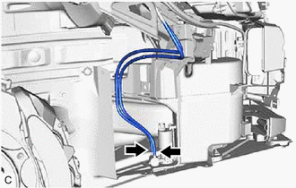
77. INSTALL WINDSHIELD WASHER JAR ASSEMBLY
|
(a) Install the 3 bolts. Torque: 5.5 N·m {56 kgf·cm, 49 in·lbf} NOTICE: Tighten the 3 bolts in the order of (A), (B) and (C). |
|
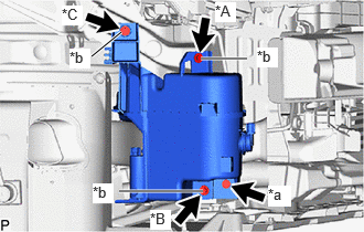
(b) Install the windshield washer jar assembly with screw.
|
(c) Engage the 2 clamps. |
|
(d) Connect the connector.
|
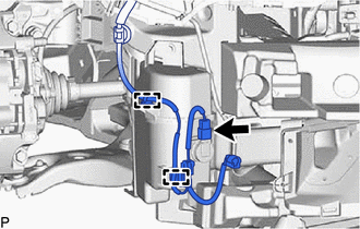
(e) Engage the clamp and 3 guides. |
|
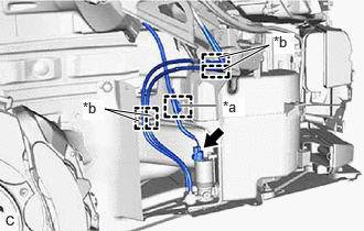
(f) Connect the connector.
|
(g) Connect the washer hose. |
|
78. INSTALL INLET HOSE
(a) Install the inlet hose as shown in the illustration.
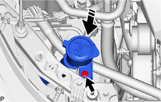

|
Install in this Direction |
(b) Install the clip.
79. ADD WASHER FLUID
Click here
80. INSTALL SUB RADIATOR ASSEMBLY WITH SUB RADIATOR DUCT (w/ Sub Radiator)
Click here
81. INSTALL FRONT BUMPER ASSEMBLY
Click here
82. INSTALL FRONT FENDER LINER RETAINER
Click here
83. INSTALL FRONT FENDER SPLASH SHIELD SUB-ASSEMBLY LH
(a) Install the 2 grommets.
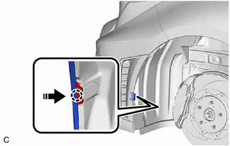
|
|
Install in this Direction |
(b) Engage the claw as shown in the illustration.
(c) Install the front fender splash shield sub-assembly LH with the 11 clips and 9 screws.
84. INSTALL PIN HOLD CLIP
(a) Engage the 2 claws as shown in the illustration to install the pin hold clip.
|
|
Install in this Direction |
85. INSTALL FRONT FENDER LINER RETAINER
HINT:
Use the same procedure for the RH side and LH side.
86. INSTALL FRONT FENDER SPLASH SHIELD SUB-ASSEMBLY RH
Click here
87. INSTALL PIN HOLD CLIP
Click here
88. CHARGE AIR CONDITIONING SYSTEM WITH REFRIGERANT
Click here
89. WARM UP ENGINE
Click here
90. ADJUST TRANSMISSION CONTROL CABLE ASSEMBLY
Click here
91. INSPECT FOR ENGINE OIL LEAK
Click here
92. INSPECT FOR MANUAL TRANSAXLE OIL LEAK (for Manual Transaxle)
Click here
93. INSPECT FOR AUTOMATIC TRANSAXLE FLUID LEAK (for Automatic Transaxle)
Click here
94. INSPECT FOR COOLANT LEAK
Click here
95. INSPECT FOR REFRIGERANT LEAK
Click here
96. INSPECT FOR FUEL LEAK
Click here
97. INSPECT FOR EXHAUST GAS LEAK
Click here
98. CHECK ENGINE OIL LEVEL
Click here
99. INSPECT RADIATOR RESERVE TANK ENGINE COOLANT LEVEL
Click here
100. INSTALL NO. 1 ENGINE UNDER COVER ASSEMBLY
(a) Install the No. 1 engine under cover assembly to the vehicle with the 4 bolts and 9 clips.
Torque:
7.5 N·m {76 kgf·cm, 66 in·lbf}
101. INSTALL FRONT WHEELS
Click here
102. ALIGN FRONT WHEELS FACING STRAIGHT AHEAD
103. INSPECT AND ADJUST FRONT WHEEL ALIGNMENT
Click here
104. PERFORM INITIALIZATION
Click here
105. INSPECT IGNITION TIMING
Click here
106. INSPECT ENGINE IDLE SPEED
Click here
107. INSPECT CO/HC
Click here
108. CHECK SPEED SENSOR SIGNAL
Click here
|
|
|