- Wireless Door Lock Control System (for Gasoline Model with Smart Key System)
- Smart Key System (for Gasoline Model, Entry Function)
- Smart Key System (for Gasoline Model, Start Function)
- Steering lock function*1
| Last Modified: 01-27-2025 | 6.11:8.1.0 | Doc ID: RM100000002Q1CC |
| Model Year Start: 2025 | Model: GR Corolla | Prod Date Range: [09/2024 - ] |
| Title: G16E-GTS (ENGINE MECHANICAL): ENGINE ASSEMBLY: REMOVAL; 2025 MY GR Corolla [09/2024 - ] | ||
REMOVAL
CAUTION / NOTICE / HINT
The necessary procedures (adjustment, calibration, initialization or registration) that must be performed after parts are removed and installed, or replaced during engine assembly removal/installation are shown below.
Necessary Procedure After Parts Removed/Installed/Replaced
|
Replaced Part or Performed Procedure |
Necessary Procedure |
Effect/Inoperative Function when Necessary Procedure not Performed |
Link |
|---|---|---|---|
|
*1:w/ Steering Lock Function
*2: Not necessary when ECM replaced with new one. *3: If transaxle compensation code read from ECM *4: If transaxle compensation code not read from ECM |
|||
|
Replacement of ECM |
Perform Vehicle Identification Number (VIN) or frame number registration |
MIL illuminates |
|
|
ECU configuration |
- |
|
|
|
Update ECU security key |
Vehicle Control History (RoB) are stored |
|
|
|
Heavy Knock History |
- |
|
|
|
ECU communication ID registration (Immobiliser system) |
Engine start function |
|
|
|
Code registration (Smart Key System (for Gasoline Model, Start Function)) |
|
|
|
for UC80F
|
|
Initialization:
Registration:
|
|
|
Inspection After Repair |
|
|
|
Automatic transaxle assembly |
|
|
Initialization:
Registration:
|
|
Automatic transaxle fluid |
ATF thermal degradation estimate reset |
The value of the Data List item "ATF Thermal Degradation Estimate" is not estimated correctly |
|
|
Front wheel alignment adjustment |
|
|
|
|
Tire |
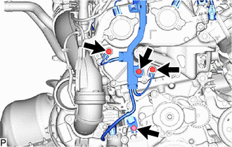
ECU Data Initialization (When performing tire replacement after RoB code X2104 is output) |
Active Torque Split AWD System |
|
CAUTION:
-
The engine assembly with transaxle is very heavy. Be sure to follow the procedure described in the repair manual, or the engine lifter may suddenly drop or the engine assembly with transaxle may fall off the engine lifter.
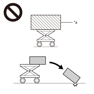
*a
An Object Exceeding Weight Limit of Engine Lifter
-
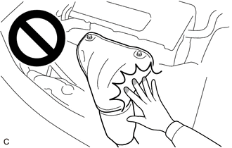
To prevent burns, do not touch the engine, exhaust manifold or other high temperature components while the engine is hot.
NOTICE:
- After the ignition switch is turned off, the radio and display receiver assembly recordsvarious types of memory and settings. As a result, after turning the ignition switch off,make sure to wait at least 3 minutes before disconnecting the cable from the negative(-) auxiliary battery terminal. (w/ Navigation System, Audio and Visual System (except Radio Receiver Type))
- When the cable is disconnected from the negative (-) auxiliary battery terminal and thesecurity lock setting has been enabled, multi-display operations will be disabled uponnext startup unless the password is entered. Be sure to check the security lock settingbefore disconnecting the cable from the negative (-) auxiliary battery terminal.(forNavigation System (for Single Knob Type), Audio and Visual System (for Single KnobType))
-
This procedure includes the removal of small-head bolts. Refer to Small-Head Bolts of Basic Repair Hint to identify the small-head bolts.
Click here
![2019 - 2025 MY Corolla Corolla Hatchback Corolla HV GR Corolla [06/2018 - ]; INTRODUCTION: REPAIR INSTRUCTION: PRECAUTION](/t3Portal/stylegraphics/info.gif)
HINT:
When the cable is disconnected / reconnected to the auxiliary battery terminal, systems temporarily stop operating. However, each system has a function that completes learning the first time the system is used.
-
Learning completes when vehicle is driven
Effect/Inoperative Function When Necessary Procedures are not Performed
Necessary Procedures
Link
Front Camera System
Drive the vehicle straight ahead at 35 km/h (22 mph) or more for 5 seconds or more.
-
Learning completes when vehicle is operated normally
Effect/Inoperative Function When Necessary Procedures are not Performed
Necessary Procedures
Link
Power door lock control system
- Back door opener
Perform door unlock operation with door control switch or electrical key transmitter sub-assembly switch.
PROCEDURE
1. PRECAUTION
NOTICE:
After turning the engine switch off, waiting time may be required before disconnecting the cable from the negative (-) auxiliary battery terminal. Therefore, make sure to read the disconnecting the cable from the negative (-) auxiliary battery terminal notices before proceeding with work.
Click here
2. RECOVER REFRIGERANT FROM REFRIGERATION SYSTEM
Click here
3. DISCHARGE FUEL SYSTEM PRESSURE
Click here
4. REMOVE DECK BOARD ASSEMBLY
Click here
5. REMOVE SPARE WHEEL CUSHION
Click here
6. DISCONNECT CABLE TO NEGATIVE BATTERY TERMINAL
Click here
7. ALIGN FRONT WHEELS FACING STRAIGHT AHEAD
8. REMOVE FRONT WHEELS
Click here
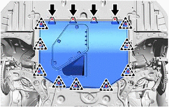
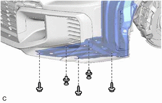
9. REMOVE NO. 1 ENGINE UNDER COVER ASSEMBLY
|
(a) Remove the 4 bolts, 9 clips and No. 1 engine under cover assembly from the vehicle. |
|
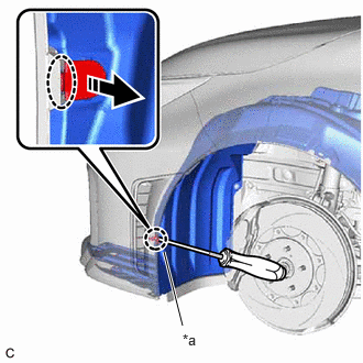
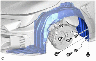
10. REMOVE FRONT FENDER SPLASH SHIELD SUB-ASSEMBLY LH
(a) Using a screwdriver with its tip wrapped with protective tape, disengage the claw as shown in the illustration.
|
*a |
Protective Tape |

|
Insert Screwdriver Here |

|
Remove in this Direction |
|
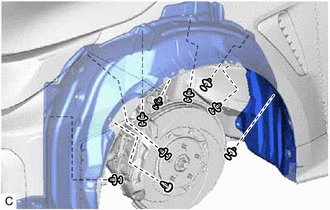
(b) Remove the 2 clips and 3 screws. |
|
|
(c) Remove the 2 grommets and 6 screws. |
|
|
(d) Remove the 9 clips and front fender splash shield sub-assembly LH. |
|
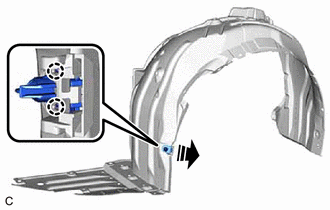
11. REMOVE PIN HOLD CLIP
(a) Disengage the 2 claws to remove the pin hold clip as shown in the illustration.
|
|
Remove in this Direction |
12. REMOVE FRONT FENDER LINER RETAINER
Click here
13. REMOVE FRONT FENDER SPLASH SHIELD SUB-ASSEMBLY RH
Click here
14. REMOVE PIN HOLD CLIP
Click here
15. REMOVE FRONT FENDER LINER RETAINER
HINT:
Use the same procedure as for the LH side.
16. REMOVE FRONT BUMPER ASSEMBLY
Click here
17. REMOVE SUB RADIATOR ASSEMBLY WITH SUB RADIATOR DUCT (w/ Sub Radiator)
Click here
18. DRAIN WASHER FLUID
Click here
19. REMOVE INLET HOSE
(a) Remove the clip.
|
|
Remove in this Direction |
(b) Remove the inlet hose as shown in the illustration.
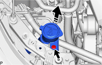
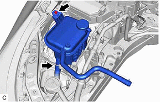
20. REMOVE WINDSHIELD WASHER JAR ASSEMBLY
|
(a) Disconnect the connector. |
|
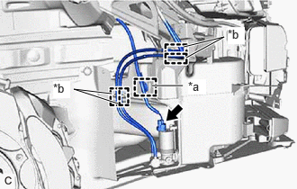
(b) Disengage the clamp and 3 guides.
|
(c) Disconnect the washer hose. |
|
|
(d) Disconnect the connector. |
|
(e) Disengage the 2 clamps.
|
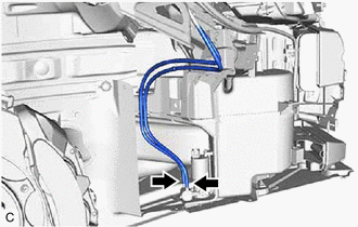
(f) Remove the screw. |
|
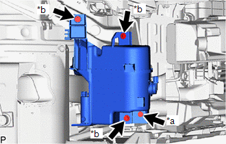
(g) Remove the 3 bolts and windshield washer jar assembly.
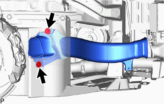
21. REMOVE NO. 2 ENGINE UNDER COVER AIR GUIDE
|
(a) Remove the 2 screws and No. 2 engine under cover air guide. |
|
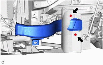
22. REMOVE NO. 3 ENGINE UNDER COVER AIR GUIDE
|
(a) Remove the bolt. |
|
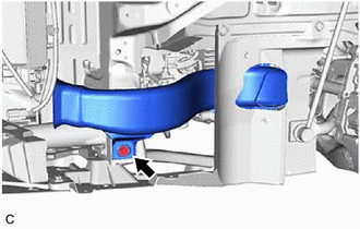
|
(b) Remove the 2 screws and No. 3 engine under cover air guide. |
|
23. REMOVE REAR ENGINE UNDER COVER LH
|
(a) Remove the 2 clips. |
|
|
(b) Remove the screw. |
|
(c) Remove the 2 clips and rear engine under cover LH from the vehicle.
24. REMOVE REAR ENGINE UNDER COVER RH
|
(a) Remove the 2 clips. |
|
|
(b) Remove the screw. |
|
(c) Remove the 2 clips and rear engine under cover RH from the vehicle.
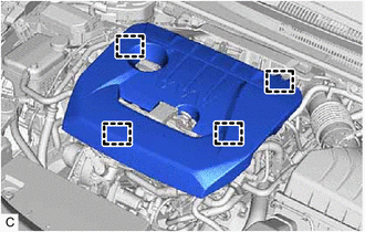
25. REMOVE NO. 1 ENGINE COVER SUB-ASSEMBLY
|
(a) Disengage the 4 clamp and remove the No. 1 engine cover sub-assembly. NOTICE: Attempting to disengage both front and rear clips at the same time may cause the No. 1 engine cover sub-assembly to break. |
|
26. DRAIN ENGINE OIL
Click here
27. DRAIN ENGINE COOLANT
Click here
28. DRAIN MANUAL TRANSAXLE OIL (for Manual Transaxle)
Click here
29. DRAIN AUTOMATIC TRANSAXLE FLUID (for Automatic Transaxle)
Click here
30. REMOVE NO. 1 AIR CLEANER INLET
Click here
31. REMOVE AIR CLEANER WITH AIR CLEANER HOSE
Click here
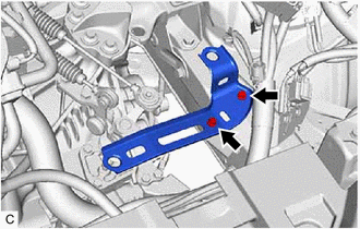
32. REMOVE AIR CLEANER BRACKET
|
(a) Remove the 2 bolts and air cleaner bracket from the vehicle. |
|
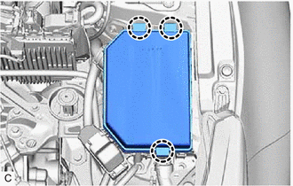
33. REMOVE NO. 1 RELAY BLOCK COVER
|
(a) Disengage the 3 claws and remove the No. 1 relay block cover from the engine room relay block. |
|
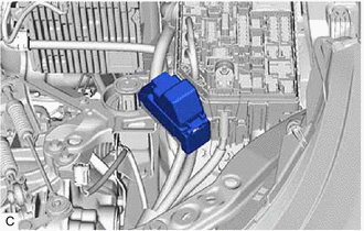
34. REMOVE COVER RELAY BLOCK UPR
|
(a) Remove the cover relay block upr . |
|
35. DISCONNECT ENGINE WIRE
|
(a) Remove the nut. |
|
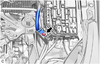
|
(b) Remove the nut. |
|
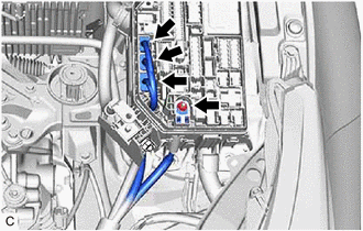
(c) Disconnect the 3 connectors from the engine room relay block.
|
(d) Remove the 2 bolts to separate the engine wire from the vehicle. |
|
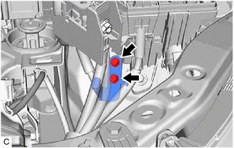
|
(e) Disengage the 2 clamps. |
|
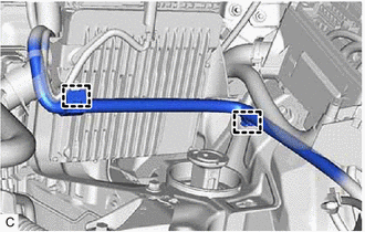
|
(f) Disengage the clamp. |
|
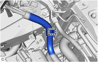
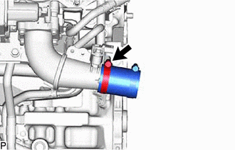
36. DISCONNECT NO. 1 RADIATOR HOSE
|
(a) Slide the clip and disconnect the No. 1 radiator hose from the water outlet. |
|
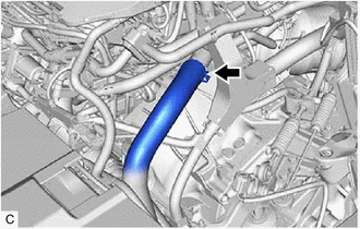
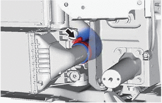
37. DISCONNECT NO. 2 RADIATOR HOSE
|
(a) Slide the clip and disconnect the No. 2 radiator hose from the water inlet with thermostat sub-assembly. |
|
38. REMOVE NO. 2 AIR TUBE
NOTICE:
If the No. 2 air tube is removed, make sure to replace the No. 4 air hose and No. 5 air hose.
|
(a) Loosen the 2 hose clamps. |
|
(b) Remove the bolt and No. 2 air tube.
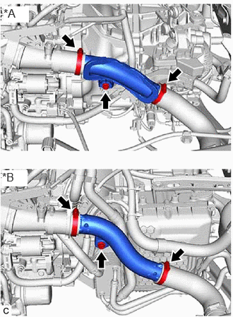
39. REMOVE NO. 4 AIR HOSE
|
(a) Loosen the hose clamp and remove the No. 4 air hose. |
|
40. REMOVE NO. 5 AIR HOSE
|
(a) Loosen the hose clamp and remove the No. 5 air hose from the air tube assembly. |
|
41. REMOVE ECM
Click here
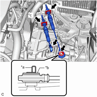
42. DISCONNECT TRANSMISSION CONTROL CABLE ASSEMBLY
|
(a) for Manual Transaxle: (1) Remove the 2 clips (A) and washer to disconnect the transmission control cable assembly from the manual transaxle assembly. (2) Remove the 2 clips (B) to disconnect the transmission control cable assembly from control cable bracket assembly. |
|
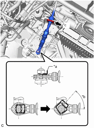
|
(b) for Automatic Transaxle: (1) While disengaging the clip (A) as shown in the illustration, disconnect the transmission control cable assembly from the transmission control shaft lever together with the clip (A). (2) Remove the clip (B) and disconnect the transmission control cable assembly from the No. 1 transmission control cable bracket. |
|
43. DISCONNECT CHECK VALVE TO CONNECTOR TUBE HOSE
Click here
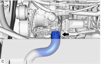
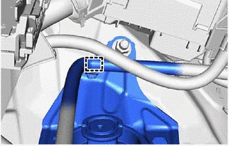
44. DISCONNECT NO. 1 WATER BY-PASS HOSE
|
(a) Slide the clip and disconnect the No. 1 water by-pass hose from the No. 4 water by-pass pipe. |
|
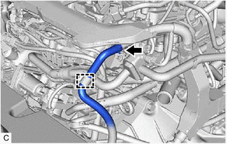
(b) Disengage the clamp.
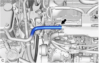
45. DISCONNECT NO. 2 WATER BY-PASS HOSE
|
(a) Slide the clip and disconnect the No. 2 water by-pass hose from the No. 4 water by-pass pipe. |
|
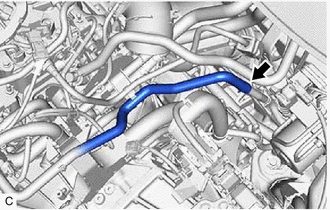
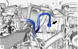
46. DISCONNECT NO. 1 FUEL VAPOR FEED HOSE
|
(a) Slide the clip and disconnect the No. 1 fuel vapor feed hose from the fuel tank to canister tube. |
|
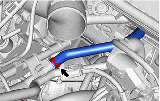
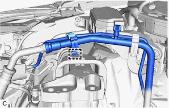
47. DISCONNECT INLET HEATER WATER HOSE
|
(a) Using pliers, grip the claws of the clip and slide the clip to disconnect the inlet heater water hose. |
|
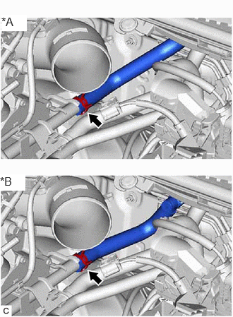
48. DISCONNECT OUTLET HEATER WATER HOSE
|
(a) Using pliers, grip the claws of the clip and slide the clip to disconnect the outlet heater water hose. |
|
49. DISCONNECT FUEL TUBE SUB-ASSEMBLY
|
(a) Remove the No. 1 fuel pipe clamp from the fuel tube sub-assembly. |
|
|
(b) Disconnect the fuel tube sub-assembly from the fuel pipe.
Click here
|
|
50. DISCONNECT SUCTION HOSE SUB-ASSEMBLY
Click here
51. DISCONNECT DISCHARGE HOSE SUB-ASSEMBLY
Click here
52. SECURE STEERING WHEEL ASSEMBLY
Click here
53. REMOVE COLUMN HOLE COVER SILENCER SHEET
Click here
54. DISCONNECT NO. 2 STEERING INTERMEDIATE SHAFT ASSEMBLY
Click here
55. REMOVE PROPELLER WITH CENTER BEARING SHAFT ASSEMBLY
Click here
56. REMOVE FRONT DRIVE SHAFT ASSEMBLY
Click here
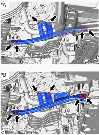
57. REMOVE REAR SIDE RAIL REINFORCEMENT SUB-ASSEMBLY LH
|
(a) for Manual Transaxle (1) Remove the 4 bolts and rear side rail reinforcement sub-assembly LH from the front suspension crossmember sub-assembly and vehicle body. |
|
|
(b) for Automatic Transaxle (1) Remove the 6 bolts and rear side rail reinforcement sub-assembly LH from the front suspension crossmember sub-assembly and vehicle body. |
|
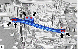
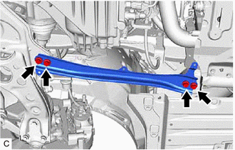
58. REMOVE REAR SIDE RAIL REINFORCEMENT SUB-ASSEMBLY RH
|
(a) Remove the 6 bolts and rear side rail reinforcement sub-assembly RH from the front suspension crossmember sub-assembly and vehicle body. |
|
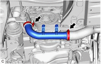
59. REMOVE NO. 1 AIR TUBE
|
(a) Lossen the 2 hose clamps and remove the No. 1 air tube. |
|
60. DISCONNECT NO. 1 CLUTCH HOSE (for Manual Transaxle)
|
(a) Using a 10 mm union nut wrench, disconnect the bleeder clutch release tube from the No. 1 clutch hose. |
|
(b) Remove the clip and disconnect the No. 1 clutch hose from the clutch flexible hose bracket.
61. DISCONNECT NO. 1 TRANSMISSION OIL COOLER HOSE ASSEMBLY (for Automatic Transaxle)
|
(a) Disengage the clamp. |
|
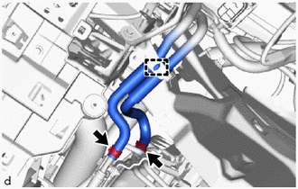
(b) Slide the 2 clips and disconnect the No. 1 transmission oil cooler hose assembly.
62. REMOVE ENGINE ASSEMBLY WITH TRANSAXLE
(a) Set the engine assembly with transaxle on an engine lifter.
NOTICE:
- Using height adjustment attachments and plate lift attachments, keep the engine assembly with transaxle and front suspension crossmember sub-assembly level.
- Do not perform any procedures while the engine assembly is suspended because doing so may cause the engine assembly to drop, resulting in injury. However, the engine assembly needs to be suspended when it is installed to or removed from an engine stand.
- To prevent the engine assembly from unexpectedly moving, securely support the engine assembly until it is secured to an engine stand.
- To prevent the No.2 oil pan sub-assembly from deforming, do not place any attachments under the No.2 oil pan sub-assembly of the engine assembly with transaxle.
|
|
Attachments |
|
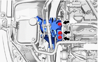
(b) Remove the 3 bolts and separate the engine mounting insulator sub-assembly RH from the engine mounting bracket RH. |
|
|
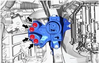
(c) Remove the 4 bolts and separate the engine mounting insulator LH from the transaxle assembly. |
|
|
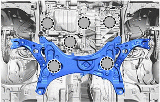
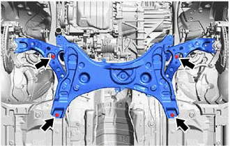
(d) Remove the 4 bolts to separate the front suspension crossmember sub-assembly from the vehicle. |
|
(e) Operate the engine lifter and remove the engine assembly with transaxle from the vehicle.
NOTICE:
- Make sure that the engine assembly with transaxle is clear of all wiring and hoses.
- While lowering the engine assembly with transaxle from the vehicle, do not allow it to contact the vehicle.
63. REMOVE ENGINE MOUNTING BRACKET CAP
(a) Turn over the engine mounting bracket cap to the upper part.
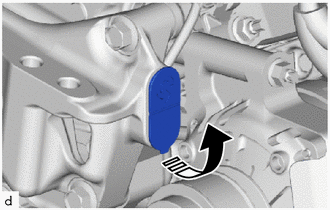
|
|
Remove in this Direction |
(b) While rotating in the direction shown in the illustration, remove the engine mounting bracket cap.
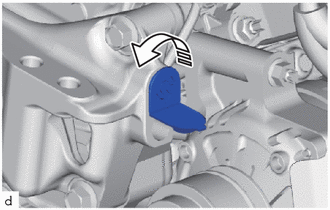

|
Rotation Direction |
64. REMOVE FLEXIBLE HOSE BRACKET (for Automatic Transaxle)
Click here
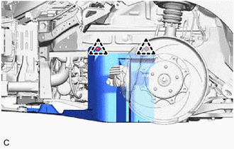
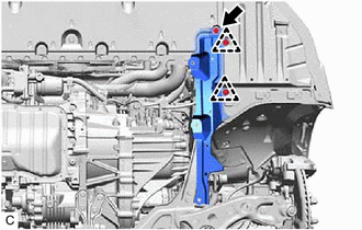
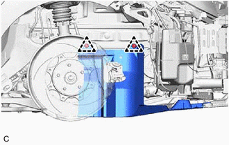
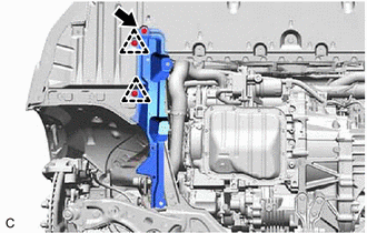
65. INSTALL ENGINE HANGERS
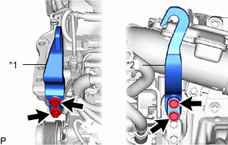
(a) Install the No. 1 engine hanger and No. 2 engine hanger with the 4 bolts as shown in the illustration.
|
*1 |
No. 1 Engine Hanger |
|
*2 |
No. 2 Engine Hanger |

|
Bolt |
Torque:
43 N·m {438 kgf·cm, 32 ft·lbf}
|
No. 1 Engine Hanger |
12281-25030 12281-25040 |
|
No. 2 Engine Hanger |
12282-18010 12282-18020 |
|
Bolt |
91552-F1045 91552-F1060 |
(b) Using an engine sling device and engine lift, secure the engine assembly with transaxle.
NOTICE:
- Pay attention to the angle of the sling device as the engine assembly or No. 1 engine hanger and No. 2 engine hanger may be damaged or deformed if the angle is incorrect.
- Do not perform any procedures while the engine assembly is suspended because doing so may cause the engine assembly to drop, resulting in injury. However, the engine assembly needs to be suspended when it is installed to or removed from an engine stand.
66. REMOVE ENGINE MOUNTING INSULATOR LH
HINT:
Perform this procedure only when replacement of the engine mounting insulator LH is necessary.
|
(a) Disengage the clamp from the engine mounting insulator LH. |
|
|
(b) Remove the 4 bolts, nut and engine mounting insulator LH from the vehicle. |
|
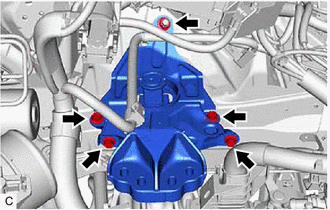
67. REMOVE RESERVE TANK ASSEMBLY
HINT:
Perform this procedure only when replacement of the engine mounting insulator sub-assembly RH is necessary.
|
(a) Slide the clip and remove the No. 3 water by-pass hose from the reserve tank assembly. |
|
(b) Remove the bolt and reserve tank assembly from the vehicle.
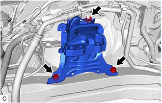
68. REMOVE ENGINE MOUNTING INSULATOR SUB-ASSEMBLY RH
HINT:
Perform this procedure only when replacement of the engine mounting insulator sub-assembly RH is necessary.
|
(a) Disengage the clamp and disconnect the air conditioner tube. |
|
|
(b) Remove the 2 bolts, nut and engine mounting insulator sub-assembly RH from the vehicle. |
|
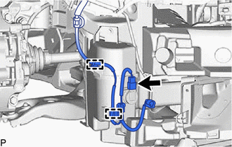
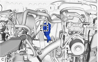
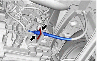
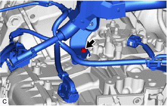
69. REMOVE NO. 1 FUEL VAPOR FEED HOSE
|
(a) Disengage the 2 clamps from the engine assembly with transaxle. |
|
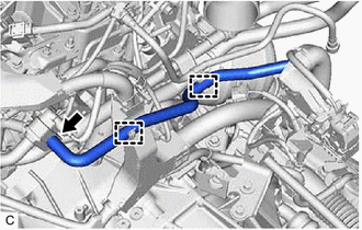
(b) Slide the clip and remove the No. 1 fuel vapor feed hose from the purge valve (purge VSV).
70. DISCONNECT TRANSMISSION OIL COOLER (for Automatic Transaxle)
Click here
71. DISCONNECT ENGINE WIRE (for Automatic Transaxle)
Click here
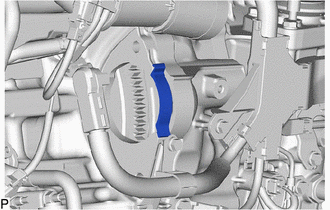
72. REMOVE FLYWHEEL HOUSING SIDE COVER
|
(a) Remove the flywheel housing side cover from the cylinder block sub-assembly. |
|
73. REMOVE STARTER ASSEMBLY
Click here
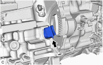
74. REMOVE FLYWHEEL HOUSING UNDER COVER
|
(a) Remove the flywheel housing under cover from the cylinder block sub-assembly. |
|
75. REMOVE FAN AND GENERATOR V BELT
Click here
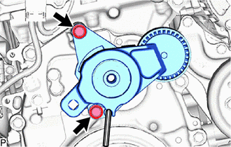
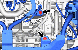
76. REMOVE V-RIBBED BELT TENSIONER ASSEMBLY
|
(a) Remove the 2 bolts and V-ribbed belt tensioner assembly from the timing chain cover assembly. |
|
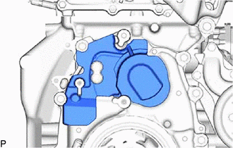
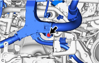
77. REMOVE TIMING GEAR COVER INSULATOR
|
(a) Remove the timing gear cover insulator from the timing chain cover assembly. |
|
78. REMOVE GENERATOR ASSEMBLY
Click here
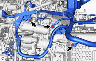
79. REMOVE NO. 5 WATER BY-PASS HOSE (for Automatic Transaxle)
|
(a) Disengage the clamp |
|
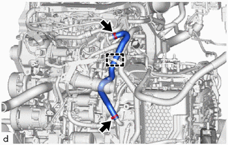
(b) Slide the 2 clips and remove the No. 5 water by-pass hose from the engine assembly with transaxle.
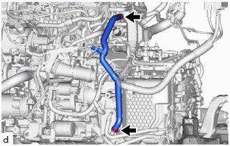
80. REMOVE NO. 4 WATER BY-PASS HOSE (for Automatic Transaxle)
|
(a) Slide the 2 clips and remove the No. 4 water by-pass hose from the engine assembly with transaxle. |
|
81. REMOVE ENGINE WIRE
(a) for Manual Transaxle:
(1) Remove the 4 bolts.
|
(2) Remove the 4 bolts. |
|
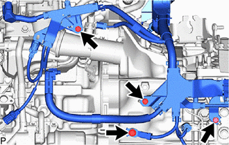
|
(3) Remove the 2 bolts. |
|
|
(4) Remove the bolt. |
|
(b) for Automatic Transaxle:
|
(1) Remove the 4 bolts. |
|
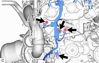
|
(2) Remove the 2 bolts. |
|
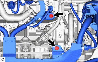
|
(3) Remove the 4 bolts. |
|
|
(4) Remove the bolt. |
|
82. REMOVE EXHAUST MANIFOLD CONVERTER SUB-ASSEMBLY
Click here
83. REMOVE PROPELLER SHAFT HEAT INSULATOR
Click here
84. REMOVE FRONT SUSPENSION CROSSMEMBER SUB-ASSEMBLY
for Manual Transaxle:
Click here
for Automatic Transaxle:
Click here
85. REMOVE DRIVE PLATE AND TORQUE CONVERTER CLUTCH SETTING BOLT (for Automatic Transaxle)
Click here
86. REMOVE AUTOMATIC TRANSAXLE ASSEMBLY (for Automatic Transaxle)
Click here
87. REMOVE DRIVE PLATE AND RING GEAR SUB-ASSEMBLY (for Automatic Transaxle)
Click here
88. REMOVE MANUAL TRANSAXLE ASSEMBLY (for Manual Transaxle)
Click here
89. REMOVE COVER AND DISC CLUTCH SET (for Manual Transaxle)
Click here
90. REMOVE FLYWHEEL SUB-ASSEMBLY (for Manual Transaxle)
Click here
91. REMOVE NO. 1 CRANKSHAFT POSITION SENSOR PLATE
Click here
92. INSTALL ENGINE ASSEMBLY TO ENGINE STAND
(a) Install the engine assembly to an engine stand.
93. REMOVE ENGINE HANGERS
(a) Remove the 4 bolts, No. 1 engine hanger and No. 2 engine hanger.
|
|
|