- Wireless Door Lock Control System (for Gasoline Model with Smart Key System)
- Smart Key System (for Gasoline Model, Entry Function)
- Smart Key System (for Gasoline Model, Start Function)
- Steering lock function*1
| Last Modified: 08-23-2025 | 6.11:8.1.0 | Doc ID: RM100000002Q1C0 |
| Model Year Start: 2025 | Model: GR Corolla | Prod Date Range: [09/2024 - ] |
| Title: G16E-GTS (ENGINE MECHANICAL): REAR CRANKSHAFT OIL SEAL: REMOVAL; 2025 - 2026 MY GR Corolla [09/2024 - ] | ||
REMOVAL
CAUTION / NOTICE / HINT
The necessary procedures (adjustment, calibration, initialization or registration) that must be performed after parts are removed and installed, or replaced during rear crankshaft oil seal removal/installation are shown below.
Necessary Procedure After Parts Removed/Installed/Replaced
|
Replaced Part or Performed Procedure |
Necessary Procedure |
Effect/Inoperative Function when Necessary Procedure not Performed |
Link |
|---|---|---|---|
|
*1:w/ Steering Lock Function
*2: Not necessary when ECM replaced with new one. *3: If transaxle compensation code read from ECM *4: If transaxle compensation code not read from ECM |
|||
|
Replacement of ECM |
Perform Vehicle Identification Number (VIN) or frame number registration |
MIL illuminates |
|
|
ECU configuration |
- |
|
|
|
Update ECU security key |
Vehicle Control History (RoB) are stored |
|
|
|
Heavy Knock History |
- |
|
|
|
ECU communication ID registration (Immobiliser system) |
Engine start function |
|
|
|
Code registration (Smart Key System (for Gasoline Model, Start Function)) |
|
|
|
for UC80F
|
|
Initialization:
Registration:
|
|
|
Inspection After Repair |
|
|
|
Automatic transaxle assembly |
|
|
Initialization:
Registration:
|
|
Automatic transaxle fluid |
ATF thermal degradation estimate reset |
The value of the Data List item "ATF Thermal Degradation Estimate" is not estimated correctly |
|
|
Front wheel alignment adjustment |
|
|
|
|
Tire |
ECU Data Initialization (When performing tire replacement after RoB code X2104 is output) |
Active Torque Split AWD System |
|
NOTICE:
This procedure includes the removal of small-head bolts. Refer to Small-Head Bolts of Basic Repair Hint to identify the small-head bolts.
Click here
![2019 - 2026 MY Corolla Corolla Hatchback Corolla HV GR Corolla [06/2018 - ]; INTRODUCTION: REPAIR INSTRUCTION: PRECAUTION](/t3Portal/stylegraphics/info.gif)
HINT:
When the cable is disconnected / reconnected to the auxiliary battery terminal, systems temporarily stop operating. However, each system has a function that completes learning the first time the system is used.
-
Learning completes when vehicle is driven
Effect/Inoperative Function When Necessary Procedures are not Performed
Necessary Procedures
Link
Front Camera System
Drive the vehicle straight ahead at 35 km/h (22 mph) or more for 5 seconds or more.
-
Learning completes when vehicle is operated normally
Effect/Inoperative Function When Necessary Procedures are not Performed
Necessary Procedures
Link
Power door lock control system
- Back door opener
Perform door unlock operation with door control switch or electrical key transmitter sub-assembly switch.
It is necessary to perform the same operation after removing and installing the system supply power fuse.
PROCEDURE
1. REMOVE COVER AND DISC CLUTCH SET (for Manual Transaxle)
Click here
2. REMOVE AUTOMATIC TRANSAXLE ASSEMBLY (for Automatic Transaxle)
Click here
3. REMOVE FLYWHEEL SUB-ASSEMBLY (for Manual Transaxle)
(a) Using height adjustment attachments and plate lift attachments, place the engine assembly on a flat level surface.
NOTICE:
- Using height adjustment attachments and plate lift attachments, keep the engine assembly level.
- To prevent the oil pan sub-assembly from deforming, do not place any attachments under the oil pan sub-assembly of the engine assembly.
- Using an engine sling device and engine lift, secure the engine assembly before servicing.
|
(b) Using SST, hold the crankshaft pulley assembly. SST: 09213-54015 SST: 09330-00021 |
|
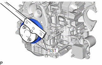
|
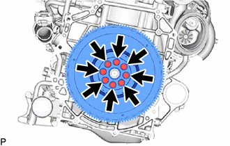
(c) Remove the 8 bolts and flywheel sub-assembly. |
|
4. REMOVE DRIVE PLATE AND RING GEAR SUB-ASSEMBLY (for Automatic Transaxle)
(a) Using height adjustment attachments and plate lift attachments, place the engine assembly on a flat level surface.
NOTICE:
- Using height adjustment attachments and plate lift attachments, keep the engine assembly level.
- To prevent the oil pan sub-assembly from deforming, do not place any attachments under the oil pan sub-assembly of the engine assembly.
- Using an engine sling device and engine lift, secure the engine assembly before servicing.
|
(b) Using SST, hold the crankshaft pulley assembly. SST: 09213-54015 SST: 09330-00021 |
|
|
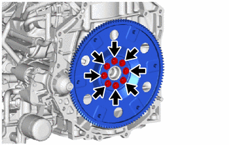
(c) Remove the 8 bolts, drive plate and ring gear sub-assembly and rear drive plate spacer. |
|
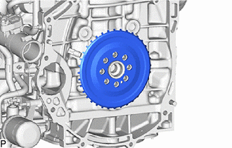
5. REMOVE NO. 1 CRANKSHAFT POSITION SENSOR PLATE
|
(a) Remove the No. 1 crankshaft position sensor plate. |
|
6. REMOVE REAR ENGINE OIL SEAL
|
(a) Using a knife, cut off the lip of the rear engine oil seal. |
|
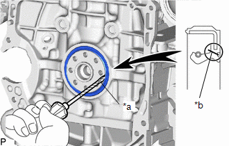
(b) Using a screwdriver, pry out the rear engine oil seal.
NOTICE:
Do not damage the surface of the rear engine oil seal press fit hole or the crankshaft.
HINT:
Tape the screwdriver tip before use.
|
|
|