- Wireless Door Lock Control System (for Gasoline Model with Smart Key System)
- Smart Key System (for Gasoline Model, Entry Function)
- Smart Key System (for Gasoline Model, Start Function)
- Steering lock function*1
| Last Modified: 01-27-2025 | 6.11:8.1.0 | Doc ID: RM100000002Q1C0 |
| Model Year Start: 2025 | Model: GR Corolla | Prod Date Range: [09/2024 - ] |
| Title: G16E-GTS (ENGINE MECHANICAL): REAR CRANKSHAFT OIL SEAL: REMOVAL; 2025 MY GR Corolla [09/2024 - ] | ||
REMOVAL
CAUTION / NOTICE / HINT
The necessary procedures (adjustment, calibration, initialization or registration) that must be performed after parts are removed and installed, or replaced during rear crankshaft oil seal removal/installation are shown below.
Necessary Procedure After Parts Removed/Installed/Replaced
|
Replaced Part or Performed Procedure |
Necessary Procedure |
Effect/Inoperative Function when Necessary Procedure not Performed |
Link |
|---|---|---|---|
|
*1:w/ Steering Lock Function
*2: Not necessary when ECM replaced with new one. *3: If transaxle compensation code read from ECM *4: If transaxle compensation code not read from ECM |
|||
|
Replacement of ECM |
Perform Vehicle Identification Number (VIN) or frame number registration |
MIL illuminates |
|
|
ECU configuration |
- |
|
|
|
Update ECU security key |
Vehicle Control History (RoB) are stored |
|
|
|
Heavy Knock History |
- |
|
|
|
ECU communication ID registration (Immobiliser system) |
Engine start function |
|
|
|
Code registration (Smart Key System (for Gasoline Model, Start Function)) |
|
|
|
for UC80F
|
|
Initialization:
Registration:
|
|
|
Inspection After Repair |
|
|
|
Automatic transaxle assembly |
|
|
Initialization:
Registration:
|
|
Automatic transaxle fluid |
ATF thermal degradation estimate reset |
The value of the Data List item "ATF Thermal Degradation Estimate" is not estimated correctly |
|
|
Front wheel alignment adjustment |
|
|
|
|
Tire |
ECU Data Initialization (When performing tire replacement after RoB code X2104 is output) |
Active Torque Split AWD System |
|
NOTICE:
This procedure includes the removal of small-head bolts. Refer to Small-Head Bolts of Basic Repair Hint to identify the small-head bolts.
Click here
![2019 - 2025 MY Corolla Corolla Hatchback Corolla HV GR Corolla [06/2018 - ]; INTRODUCTION: REPAIR INSTRUCTION: PRECAUTION](/t3Portal/stylegraphics/info.gif)
HINT:
When the cable is disconnected / reconnected to the auxiliary battery terminal, systems temporarily stop operating. However, each system has a function that completes learning the first time the system is used.
-
Learning completes when vehicle is driven
Effect/Inoperative Function When Necessary Procedures are not Performed
Necessary Procedures
Link
Front Camera System
Drive the vehicle straight ahead at 35 km/h (22 mph) or more for 5 seconds or more.
-
Learning completes when vehicle is operated normally
Effect/Inoperative Function When Necessary Procedures are not Performed
Necessary Procedures
Link
Power door lock control system
- Back door opener
Perform door unlock operation with door control switch or electrical key transmitter sub-assembly switch.
PROCEDURE
1. REMOVE COVER AND DISC CLUTCH SET (for Manual Transaxle)
Click here
2. REMOVE AUTOMATIC TRANSAXLE ASSEMBLY (for Automatic Transaxle)
Click here
3. REMOVE FLYWHEEL SUB-ASSEMBLY (for Manual Transaxle)
(a) Using height adjustment attachments and plate lift attachments, place the engine assembly on a flat level surface.
NOTICE:
- Using height adjustment attachments and plate lift attachments, keep the engine assembly level.
- To prevent the oil pan sub-assembly from deforming, do not place any attachments under the oil pan sub-assembly of the engine assembly.
- Using an engine sling device and engine lift, secure the engine assembly before servicing.
|
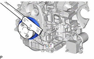
(b) Using SST, hold the crankshaft pulley assembly. SST: 09213-54015 SST: 09330-00021 |
|
|
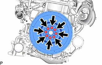
(c) Remove the 8 bolts and flywheel sub-assembly. |
|
4. REMOVE DRIVE PLATE AND RING GEAR SUB-ASSEMBLY (for Automatic Transaxle)
(a) Using height adjustment attachments and plate lift attachments, place the engine assembly on a flat level surface.
NOTICE:
- Using height adjustment attachments and plate lift attachments, keep the engine assembly level.
- To prevent the oil pan sub-assembly from deforming, do not place any attachments under the oil pan sub-assembly of the engine assembly.
- Using an engine sling device and engine lift, secure the engine assembly before servicing.
|
(b) Using SST, hold the crankshaft pulley assembly. SST: 09213-54015 SST: 09330-00021 |
|
|
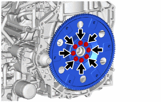
(c) Remove the 8 bolts, drive plate and ring gear sub-assembly and rear drive plate spacer. |
|
5. REMOVE NO. 1 CRANKSHAFT POSITION SENSOR PLATE
|
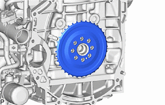
(a) Remove the No. 1 crankshaft position sensor plate. |
|
6. REMOVE REAR ENGINE OIL SEAL
|
(a) Using a knife, cut off the lip of the rear engine oil seal. |
|
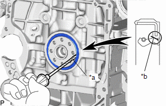
(b) Using a screwdriver, pry out the rear engine oil seal.
NOTICE:
Do not damage the surface of the rear engine oil seal press fit hole or the crankshaft.
HINT:
Tape the screwdriver tip before use.
|
|
|