| Last Modified: 01-27-2025 | 6.11:8.1.0 | Doc ID: RM100000002PAPN |
| Model Year Start: 2025 | Model: GR Corolla | Prod Date Range: [09/2024 - ] |
| Title: EA67F / EA68F (MANUAL TRANSMISSION / TRANSAXLE): MANUAL TRANSAXLE SYSTEM: Drive Mode Select Switch Circuit; 2025 MY Corolla Corolla Hatchback GR Corolla [09/2024 - ] | ||
|
Drive Mode Select Switch Circuit |
SYSTEM DESCRIPTION
The ECM changes between Normal, Sport and Eco drive mode in accordance with the output of the drive mode select switch (combination switch assembly).
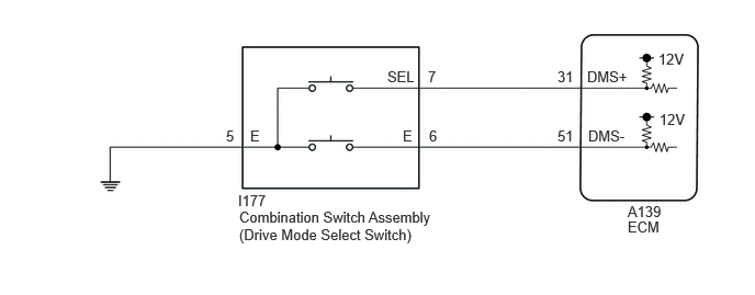
WIRING DIAGRAM
PROCEDURE
|
1. |
READ VALUE USING TECHSTREAM (DRIVE MODE SELECT SWITCH (DMS+) AND DRIVE MODE SELECT SWITCH (DMS-)) |
(a) According to the display on the Techstream, read the Data List.
Powertrain > Engine > Data List
|
Tester Display |
Measurement Item |
Range |
Normal Condition |
Diagnostic Note |
|---|---|---|---|---|
|
Drive Mode Select Switch (DMS+) |
Drive mode select switch (combination switch assembly) status |
ON or OFF |
|
- |
|
Drive Mode Select Switch (DMS-) |
Drive mode select switch (combination switch assembly) status |
ON or OFF |
|
- |
Powertrain > Engine > Data List
|
Tester Display |
|---|
|
Drive Mode Select Switch (DMS+) |
|
Drive Mode Select Switch (DMS-) |
|
Result |
Proceed to |
|---|---|
|
Data List value is normal |
A |
|
Data List value is not normal |
B |
| A |

|
|

|
2. |
INSPECT COMBINATION SWITCH ASSEMBLY (DRIVE MODE SELECT SWITCH) |
(a) Inspect the combination switch assembly.
Click here
![2025 MY Corolla Corolla Hatchback GR Corolla [09/2024 - ]; EA67F / EA68F (MANUAL TRANSMISSION / TRANSAXLE): PATTERN SELECT SWITCH: INSPECTION](/t3Portal/stylegraphics/info.gif)
| NG |
|
REPLACE COMBINATION SWITCH ASSEMBLY (DRIVE MODE SELECT SWITCH) |
|
|
3. |
CHECK HARNESS AND CONNECTOR (COMBINATION SWITCH ASSEMBLY - BODY GROUND) |
(a) Disconnect the I177 combination switch assembly connector.
(b) Measure the resistance according to the value(s) in the table below.
Standard Resistance:
|
Tester Connection |
Condition |
Specified Condition |
|---|---|---|
|
I177-5 (E) - Body ground |
Always |
Below 1 Ω |
(c) Connect the I177 combination switch assembly connector.
| NG |
|
REPAIR OR REPLACE HARNESS OR CONNECTOR (COMBINATION SWITCH ASSEMBLY - BODY GROUND) |
|
|
4. |
CHECK HARNESS AND CONNECTOR (COMBINATION SWITCH ASSEMBLY - ECM) |
(a) Disconnect the A139 ECM connector.
(b) Measure the resistance according to the value(s) in the table below.
Standard Resistance:
|
Tester Connection |
Condition |
Specified Condition |
|---|---|---|
|
A139-31 (DMS+) - Body ground |
Drive mode select switch pushed forward |
Below 50 Ω |
|
A139-31 (DMS+) - Body ground |
Drive mode select switch in neutral position |
10 kΩ or higher |
|
A139-51 (DMS-) - Body ground |
Drive mode select switch pulled rearward |
Below 50 Ω |
|
A139-51 (DMS-) - Body ground |
Drive mode select switch in neutral position |
10 kΩ or higher |
(c) Connect the A139 ECM connector.
| OK |
|
| NG |
|
REPAIR OR REPLACE HARNESS OR CONNECTOR (COMBINATION SWITCH ASSEMBLY - ECM) |
|
|
|