- Poor idle, etc.
- Engine start function, etc.
| Last Modified: 01-27-2025 | 6.11:8.1.0 | Doc ID: RM100000002PAC7 |
| Model Year Start: 2025 | Model: GR Corolla | Prod Date Range: [09/2024 - ] |
| Title: REAR SUSPENSION: REAR STABILIZER BAR (for Hatchback Gasoline Model AWD): REMOVAL; 2025 MY Corolla Corolla Hatchback GR Corolla [09/2024 - ] | ||
REMOVAL
CAUTION / NOTICE / HINT
The necessary procedures (adjustment, calibration, initialization, or registration) that must be performed after parts are removed and installed, or replaced during rear stabilizer bar removal/installation are shown below.
Necessary Procedures After Parts Removed/Installed/Replaced
|
Replaced Part or Performed Procedure |
Necessary Procedure |
Effect/Inoperative Function when Necessary Procedure not Performed |
Link |
|---|---|---|---|
|
Tire |
ECU Data Initialization (When performing tire replacement after RoB code X2104 is output) |
Active Torque Split AWD System |
|
|
Gas leaks from exhaust system is repaired (G16E-GTS) |
Inspection after repair |
|
|
CAUTION:
To prevent burns, do not touch the engine, exhaust pipe or other high temperature components while the engine is hot. (for Gasoline Model AWD)
PROCEDURE
1. REMOVE REAR WHEEL
Click here
![2023 - 2025 MY Corolla Corolla Hatchback Corolla HV GR Corolla [09/2022 - ]; MAINTENANCE: TIRE AND WHEEL: REMOVAL](/t3Portal/stylegraphics/info.gif)
2. REMOVE EXHAUST PIPE GAS CONTROL ACTUATOR SUB-ASSEMBLY
Click here
3. REMOVE TAIL EXHAUST PIPE ASSEMBLY
Click here
4. REMOVE FRONT FLOOR COVER LH
Click here
5. REMOVE REAR FLOOR SIDE MEMBER COVER LH
Click here
6. REMOVE FRONT FLOOR COVER RH
Click here
7. REMOVE REAR FLOOR SIDE MEMBER COVER RH
Click here
8. REMOVE REAR STABILIZER BAR
|
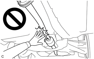
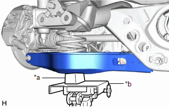
(a) Using a transmission jack and a wooden block, support the rear No. 2 suspension arm assembly. NOTICE:
HINT:
|
|
|
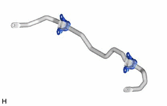
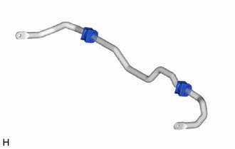
(b) Remove the 4 bolts, rear stabilizer bar, 2 rear No. 1 stabilizer bar brackets and 2 rear stabilizer bushings from the rear suspension member sub-assembly. |
|
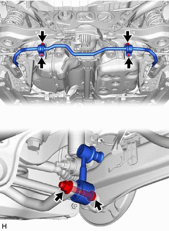
(c) Remove the 2 bolts, 2 nuts and rear stabilizer bar from the rear stabilizer link assembly LH and rear stabilizer link assembly RH.
9. REMOVE REAR STABILIZER LINK ASSEMBLY LH
(a) Remove the cap from the rear stabilizer link assembly LH.
|
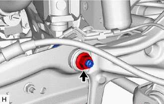
(b) Remove the nut and rear stabilizer link assembly LH from the rear trailing arm assembly. HINT: If the ball joint turns together with the nut, use a 6 mm hexagon socket wrench to hold the stud bolt. |
|
10. REMOVE REAR STABILIZER LINK ASSEMBLY RH
HINT:
Perform the same procedure as for the LH side.
11. REMOVE REAR NO. 1 STABILIZER BAR BRACKET
|
(a) Remove the 2 rear No. 1 stabilizer bar brackets from the 2 rear stabilizer bushings. |
|
12. REMOVE REAR STABILIZER BUSHING
|
(a) Remove the 2 rear stabilizer bushings from the rear stabilizer bar. |
|
|
|
|