| Last Modified: 01-27-2025 | 6.11:8.1.0 | Doc ID: RM100000002P6AS |
| Model Year Start: 2025 | Model: GR Corolla | Prod Date Range: [09/2024 - ] |
| Title: PARK ASSIST / MONITORING: PARKING SUPPORT BRAKE SYSTEM: U117787,U117887; Lost Communication with Side Obstacle Detection Control Module "A" (ch2) Missing Message; 2025 MY Corolla Corolla Hatchback Corolla HV GR Corolla [09/2024 - ] | ||
|
DTC |
U117787 |
Lost Communication with Side Obstacle Detection Control Module "A" (ch2) Missing Message |
|
DTC |
U117887 |
Lost Communication with Side Obstacle Detection Control Module "B" (ch2) Missing Message |
DESCRIPTION
This DTC is output when the clearance warning ECU assembly detects lost communication with the blind spot monitor sensor.
|
DTC No. |
Detection Item |
DTC Detection Condition |
Trouble Area |
DTC Output from |
Priority |
|---|---|---|---|---|---|
|
U117787 |
Lost Communication with Side Obstacle Detection Control Module "A" (ch2) Missing Message |
The clearance warning ECU assembly is unable to receive communication from the blind spot monitor sensor RH (A) |
|
Clearance Warning |
A |
|
U117887 |
Lost Communication with Side Obstacle Detection Control Module "B" (ch2) Missing Message |
The clearance warning ECU assembly is unable to receive communication from the blind spot monitor sensor LH (B) |
|
Clearance Warning |
A |
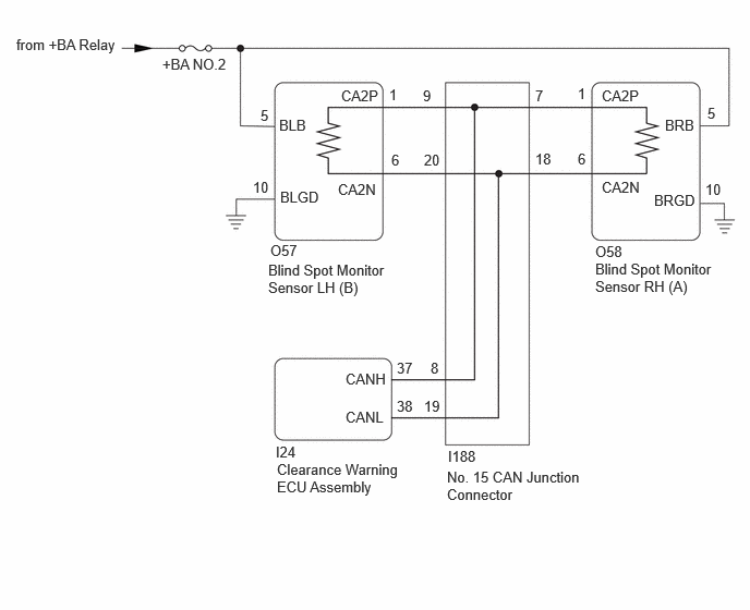
WIRING DIAGRAM
CAUTION / NOTICE / HINT
NOTICE:
- Inspect the fuses for circuits related to this system before performing the following procedure.
- Before measuring the resistance of the CAN bus, turn the ignition switch off and leave the vehicle for 1 minute or more without operating the key or any switches, or opening or closing the doors. After that, disconnect the cable from the negative (-) auxiliary battery terminal and leave the vehicle for 1 minute or more before measuring the resistance.
-
After the ignition switch is turned off, there may be a waiting time before disconnecting the negative (-) auxiliary battery terminal.
Click here
![2023 - 2025 MY Corolla Corolla Hatchback Corolla HV GR Corolla [09/2022 - ]; SETUP: WHEN DISCONNECTING OR RECONNECTING BATTERY TERMINAL: BEFORE DISCONNECTING BATTERY](/t3Portal/stylegraphics/info.gif)
-
When disconnecting and reconnecting the auxiliary battery
HINT:
When disconnecting and reconnecting the auxiliary battery, there is an automatic learning function that completes learning when the respective system is used.
Click here
HINT:
- Operating the ignition switch, any other switches or a door triggers related ECU and sensor communication on the CAN. This communication will cause the resistance value to change.
- Even after DTCs are cleared, if a DTC is stored again after driving the vehicle for a while, the malfunction may be occurring due to vibration of the vehicle. In such a case, wiggling the ECUs or wire harness while performing the inspection below may help determine the cause of the malfunction.
PROCEDURE
|
1. |
CLEAR DTC |
(a) Clear the DTCs.
Body Electrical > Clearance Warning > Clear DTCs
|

|
2. |
CHECK FOR DTC |
(a) Check for DTCs.
Body Electrical > Clearance Warning > Trouble Codes
|
Result |
Proceed to |
|---|---|
|
DTCs are not output |
A |
|
Only U117787 is output |
B |
|
Only U117887 is output |
C |
|
U117787 and U117887 are output |
D |
| A |

|
| C |
|
| D |
|
|
|
3. |
CHECK HARNESS AND CONNECTOR (BLIND SPOT MONITOR SENSOR RH (A) - AUXILIARY BATTERY AND BODY GROUND) |
Pre-procedure1
(a) Disconnect the O58 blind spot monitor sensor RH (A) connector.
Procedure1
(b) Measure the resistance according to the value(s) in the table below.
Standard Resistance:
|
Tester Connection |
Condition |
Specified Condition |
|---|---|---|
|
O58-10 (BRGD) - Body ground |
Always |
Below 1 Ω |
(c) Measure the voltage according to the value(s) in the table below.
Standard Voltage:
|
Tester Connection |
Switch Condition |
Specified Condition |
|---|---|---|
|
O58-5 (BRB) - Body ground |
Ignition switch ON |
11 to 14 V |
|
O58-5 (BRB) - Body ground |
Ignition switch off |
Below 1 V |
Post-procedure1
(d) None
| NG |
|
REPAIR OR REPLACE HARNESS OR CONNECTOR |
|
|
4. |
CHECK FOR OPEN IN CAN BUS MAIN WIRE (BLIND SPOT MONITOR SENSOR RH [A]) |
Pre-procedure1
(a) Disconnect the cable from the negative (-) auxiliary battery terminal.
(b) Disconnect the O58 blind spot monitor sensor RH (A) connector.
Procedure1
(c) Measure the resistance according to the value(s) in the table below.
Standard Resistance:
|
Tester Connection |
Condition |
Specified Condition |
|---|---|---|
|
O58-1 (CA2P) - O58-6 (CA2N) |
Cable disconnected from negative (-) auxiliary battery terminal |
108 to 132 Ω |
Post-procedure1
(d) None
| OK |
|
|
|
5. |
CHECK FOR OPEN IN CAN BUS MAIN WIRE (NO. 15 CAN JUNCTION CONNECTOR) |
Pre-procedure1
(a) Reconnect the O58 blind spot monitor sensor RH (A) connector.
(b) Disconnect the I188 No. 15 CAN junction connector.
Procedure1
(c) Measure the resistance according to the value(s) in the table below.
Standard Resistance:
|
Tester Connection |
Condition |
Specified Condition |
|---|---|---|
|
I188-7 (CANH) - I188-18 (CANL) |
Cable disconnected from negative (-) auxiliary battery terminal |
108 to 132 Ω |
Post-procedure1
(d) None
| OK |
|
REPLACE NO. 15 CAN JUNCTION CONNECTOR |
| NG |
|
REPAIR OR REPLACE CAN MAIN WIRE OR CONNECTOR (BLIND SPOT MONITOR SENSOR RH [A] - NO. 15 CAN JUNCTION CONNECTOR) |
|
6. |
CHECK HARNESS AND CONNECTOR (BLIND SPOT MONITOR SENSOR LH (B) - AUXILIARY BATTERY AND BODY GROUND) |
Pre-procedure1
(a) Disconnect the O57 blind spot monitor sensor LH (B) connector.
(b) Measure the resistance according to the value(s) in the table below.
Standard Resistance:
|
Tester Connection |
Condition |
Specified Condition |
|---|---|---|
|
O57-10 (BLGD) - Body ground |
Always |
Below 1 Ω |
Procedure1
(c) Measure the voltage according to the value(s) in the table below.
Standard Voltage:
|
Tester Connection |
Switch Condition |
Specified Condition |
|---|---|---|
|
O57-5 (BLB) - Body ground |
Ignition switch ON |
11 to 14 V |
|
O57-5 (BLB) - Body ground |
Ignition switch off |
Below 1 V |
Post-procedure1
(d) None
| NG |
|
REPAIR OR REPLACE HARNESS OR CONNECTOR |
|
|
7. |
CHECK FOR OPEN IN CAN BUS MAIN WIRE (BLIND SPOT MONITOR SENSOR LH [B]) |
Pre-procedure1
(a) Disconnect the cable from the negative (-) auxiliary battery terminal.
(b) Disconnect the O57 blind spot monitor sensor LH (B) connector.
Procedure1
(c) Measure the resistance according to the value(s) in the table below.
Standard Resistance:
|
Tester Connection |
Condition |
Specified Condition |
|---|---|---|
|
O57-1 (CA2P) - O57-6 (CA2N) |
Cable disconnected from negative (-) auxiliary battery terminal |
108 to 132 Ω |
Post-procedure1
(d) None
| OK |
|
|
|
8. |
CHECK FOR OPEN IN CAN BUS MAIN WIRE (NO. 15 CAN JUNCTION CONNECTOR) |
Pre-procedure1
(a) Reconnect the O57 blind spot monitor sensor LH (B) connector.
(b) Disconnect the I188 No. 15 CAN junction connector.
Procedure1
(c) Measure the resistance according to the value(s) in the table below.
Standard Resistance:
|
Tester Connection |
Condition |
Specified Condition |
|---|---|---|
|
I188-9 (CANH) - I188-20 (CANL) |
Cable disconnected from negative (-) auxiliary battery terminal |
108 to 132 Ω |
Post-procedure1
(d) None
| OK |
|
REPLACE NO. 15 CAN JUNCTION CONNECTOR |
| NG |
|
REPAIR OR REPLACE CAN MAIN WIRE OR CONNECTOR (BLIND SPOT MONITOR SENSOR LH [B] - NO. 15 CAN JUNCTION CONNECTOR) |
|
9. |
CHECK CAN BUS MAIN WIRE |
Pre-procedure1
(a) Disconnect the cable from the negative (-) auxiliary battery terminal.
(b) Disconnect the I24 clearance warning ECU connector.
Procedure1
(c) Measure the resistance according to the value(s) in the table below.
Standard Resistance:
|
Tester Connection |
Condition |
Specified Condition |
|---|---|---|
|
I24-37 (CANH) - I24-38 (CANL) |
Cable disconnected from negative (-) auxiliary battery terminal |
54 to 69 Ω |
|
I24-37 (CANH) - I26-4 (CG) |
Cable disconnected from negative (-) auxiliary battery terminal |
200 Ω or higher |
|
I24-38 (CANL) - I26-4 (CG) |
Cable disconnected from negative (-) auxiliary battery terminal |
200 Ω or higher |
|
I24-37 (CANH) - I26-16 (BAT) |
Cable disconnected from negative (-) auxiliary battery terminal |
6 kΩ or higher |
|
I24-38 (CANL) - I26-16 (BAT) |
Cable disconnected from negative (-) auxiliary battery terminal |
6 kΩ or higher |
|
Result |
Proceed to |
|---|---|
|
I24-37 (CANH) - I24-38 (CANL) is more than or equal to 70 Ω |
A |
|
I24-37 (CANH) - I24-38 (CANL) is less than or equal to 54 Ω |
B |
|
I24-37 (CANH) - I26-4 (CG) is less than or equal to 200 Ω |
C |
|
I24-38 (CANL) - I26-4 (CG) is less than or equal to 200 Ω |
D |
|
I24-37 (CANH) - I26-16 (BAT) is less than or equal to 6 kΩ |
E |
|
I24-38 (CANL) - I26-16 (BAT) is less than or equal to 6 kΩ |
F |
|
None of the above conditions are met |
G |
Post-procedure1
(d) None
| B |
|
| C |
|
| D |
|
| E |
|
| F |
|
| G |
|
|
|
10. |
CHECK FOR OPEN IN CAN BUS WIRE (NO. 15 CAN JUNCTION CONNECTOR) |
Pre-procedure1
(a) Disconnect the I188 No. 15 CAN junction connector.
Procedure1
(b) Measure the resistance according to the value(s) in the table below.
Standard Resistance:
|
Tester Connection |
Condition |
Specified Condition |
|---|---|---|
|
I188-9 (CANH) - I188-20 (CANL) |
Cable disconnected from negative (-) auxiliary battery terminal |
108 to 132 Ω |
Post-procedure1
(c) None
| NG |
|
|
|
11. |
CHECK FOR OPEN IN CAN BUS WIRE (NO. 15 CAN JUNCTION CONNECTOR) |
Pre-procedure1
(a) Disconnect the I188 No. 15 CAN junction connector.
Procedure1
(b) Measure the resistance according to the value(s) in the table below.
Standard Resistance:
|
Tester Connection |
Condition |
Specified Condition |
|---|---|---|
|
I188-7 (CANH) - I188-18 (CANL) |
Cable disconnected from negative (-) auxiliary battery terminal |
108 to 132 Ω |
Post-procedure1
(c) None
| NG |
|
|
|
12. |
CHECK FOR OPEN IN CAN BUS WIRE (NO. 15 CAN JUNCTION CONNECTOR) |
Pre-procedure1
(a) Reconnect the I188 No. 15 CAN junction connector.
Procedure1
(b) Measure the resistance according to the value(s) in the table below.
Standard Resistance:
|
Tester Connection |
Condition |
Specified Condition |
|---|---|---|
|
I188-8 (CANH) - I188-19 (CANL) |
Cable disconnected from negative (-) auxiliary battery terminal |
54 to 69 Ω |
Post-procedure1
(c) None
| OK |
|
REPAIR OR REPLACE CAN BUS WIRE (CLEARANCE WARNING ECU ASSEMBLY - NO. 15 CAN JUNCTION CONNECTOR) |
| NG |
|
REPLACE NO. 15 CAN JUNCTION CONNECTOR |
|
13. |
CHECK FOR OPEN IN CAN BUS MAIN WIRE (BLIND SPOT MONITOR SENSOR LH (B)) |
Pre-procedure1
(a) Reconnect the I188 No. 15 CAN junction connector.
(b) Disconnect the O57 blind spot monitor sensor LH (B) connector.
Procedure1
(c) Measure the resistance according to the value(s) in the table below.
Standard Resistance:
|
Tester Connection |
Condition |
Specified Condition |
|---|---|---|
|
O57-1 (CA2P) - O57-6 (CA2N) |
Cable disconnected from negative (-) auxiliary battery terminal |
108 to 132 Ω |
Post-procedure1
(d) None
| OK |
|
| NG |
|
REPAIR OR REPLACE CAN MAIN WIRE OR CONNECTOR (BLIND SPOT MONITOR SENSOR LH (B) - NO. 15 CAN JUNCTION CONNECTOR) |
|
14. |
CHECK FOR OPEN IN CAN BUS MAIN WIRE (BLIND SPOT MONITOR SENSOR RH (A)) |
Pre-procedure1
(a) Reconnect the I188 No. 15 CAN junction connector.
(b) Disconnect the O58 blind spot monitor sensor RH (A) connector.
Procedure1
(c) Measure the resistance according to the value(s) in the table below.
Standard Resistance:
|
Tester Connection |
Condition |
Specified Condition |
|---|---|---|
|
O58-1 (CA2P) - O58-6 (CA2N) |
Cable disconnected from negative (-) auxiliary battery terminal |
108 to 132 Ω |
Post-procedure1
(d) None
| OK |
|
| NG |
|
REPAIR OR REPLACE CAN MAIN WIRE OR CONNECTOR (BLIND SPOT MONITOR SENSOR RH (A) - NO. 15 CAN JUNCTION CONNECTOR) |
|
15. |
CHECK FOR SHORT IN CAN BUS WIRES (NO. 15 CAN JUNCTION CONNECTOR) |
Pre-procedure1
(a) Disconnect the I188 No. 15 CAN junction connector.
Procedure1
(b) Measure the resistance according to the value(s) in the table below.
Standard Resistance:
|
Tester Connection |
Condition |
Specified Condition |
|---|---|---|
|
I188-9 (CANH) - I188-20 (CANL) |
Cable disconnected from negative (-) auxiliary battery terminal |
108 to 132 Ω |
Post-procedure1
(c) None
| NG |
|
|
|
16. |
CHECK FOR SHORT IN CAN BUS WIRES (NO. 15 CAN JUNCTION CONNECTOR) |
Pre-procedure1
(a) Disconnect the I188 No. 15 CAN junction connector.
Procedure1
(b) Measure the resistance according to the value(s) in the table below.
Standard Resistance:
|
Tester Connection |
Condition |
Specified Condition |
|---|---|---|
|
I188-7 (CANH) - I188-18 (CANL) |
Cable disconnected from negative (-) auxiliary battery terminal |
108 to 132 Ω |
Post-procedure1
(c) None
| NG |
|
|
|
17. |
CHECK FOR SHORT IN CAN BUS WIRES (NO. 15 CAN JUNCTION CONNECTOR) |
Pre-procedure1
(a) Disconnect the I188 No. 15 CAN junction connector.
Procedure1
(b) Measure the resistance according to the value(s) in the table below.
Standard Resistance:
|
Tester Connection |
Condition |
Specified Condition |
|---|---|---|
|
I188-8 (CANH) - I188-19 (CANL) |
Cable disconnected from negative (-) auxiliary battery terminal |
200 Ω or higher |
Post-procedure1
(c) None
| OK |
|
REPLACE NO. 15 CAN JUNCTION CONNECTOR |
| NG |
|
|
18. |
CHECK FOR SHORT IN CAN BUS WIRES (BLIND SPOT MONITOR SENSOR LH (B)) |
Pre-procedure1
(a) Reconnect the I188 No. 15 CAN junction connector.
(b) Disconnect the O57 blind spot monitor sensor LH (B) connector.
Procedure1
(c) Measure the resistance according to the value(s) in the table below.
Standard Resistance:
|
Tester Connection |
Condition |
Specified Condition |
|---|---|---|
|
O57-1 (CA2P) - O57-6 (CA2N) |
Cable disconnected from negative (-) auxiliary battery terminal |
108 to 132 Ω |
Post-procedure1
(d) None
| OK |
|
| NG |
|
REPAIR OR REPLACE CAN MAIN WIRE OR CONNECTOR (BLIND SPOT MONITOR SENSOR LH (B) - NO. 15 CAN JUNCTION CONNECTOR) |
|
19. |
CHECK FOR SHORT IN CAN BUS WIRES (BLIND SPOT MONITOR SENSOR RH (A)) |
Pre-procedure1
(a) Reconnect the I188 No. 15 CAN junction connector.
(b) Disconnect the O58 blind spot monitor sensor RH (A) connector.
Procedure1
(c) Measure the resistance according to the value(s) in the table below.
Standard Resistance:
|
Tester Connection |
Condition |
Specified Condition |
|---|---|---|
|
O58-1 (CA2P) - O58-6 (CA2N) |
Cable disconnected from negative (-) auxiliary battery terminal |
108 to 132 Ω |
Post-procedure1
(d) None
| OK |
|
| NG |
|
REPAIR OR REPLACE CAN MAIN WIRE OR CONNECTOR (BLIND SPOT MONITOR SENSOR RH (A) - NO. 15 CAN JUNCTION CONNECTOR) |
|
20. |
CHECK FOR SHORT IN CAN BUS WIRES (CLEARANCE WARNING ECU ASSEMBLY) |
Pre-procedure1
(a) Reconnect the I188 No. 15 CAN junction connector.
(b) Disconnect the I24 clearance warning ECU connector.
Procedure1
(c) Measure the resistance according to the value(s) in the table below.
Standard Resistance:
|
Tester Connection |
Condition |
Specified Condition |
|---|---|---|
|
I24-37 (CANH) - I24-38 (CANL) |
Cable disconnected from negative (-) auxiliary battery terminal |
54 to 69 Ω |
Post-procedure1
(d) None
| OK |
|
| NG |
|
REPAIR OR REPLACE CAN BUS WIRE (CLEARANCE WARNING ECU ASSEMBLY - NO. 15 CAN JUNCTION CONNECTOR) |
|
21. |
CHECK FOR SHORT IN CAN BUS WIRES (NO. 15 CAN JUNCTION CONNECTOR) |
Pre-procedure1
(a) Disconnect the I188 No. 15 CAN junction connector.
Procedure1
(b) Measure the resistance according to the value(s) in the table below.
Standard Resistance:
|
Tester Connection |
Condition |
Specified Condition |
|---|---|---|
|
I188-9 (CANH) - I26-4 (CG) |
Cable disconnected from negative (-) auxiliary battery terminal |
200 Ω or higher |
|
I188-20 (CANL) - I26-4 (CG) |
Cable disconnected from negative (-) auxiliary battery terminal |
200 Ω or higher |
|
I188-9 (CANH) - I26-16 (BAT) |
Cable disconnected from negative (-) auxiliary battery terminal |
6 kΩ or higher |
|
I188-20 (CANL) - I26-16 (BAT) |
Cable disconnected from negative (-) auxiliary battery terminal |
6 kΩ or higher |
HINT:
Check for short that was confirmed to be a malfunction by confirming symptoms.
Post-procedure1
(c) None
| NG |
|
|
|
22. |
CHECK FOR SHORT IN CAN BUS WIRES (NO. 15 CAN JUNCTION CONNECTOR) |
Pre-procedure1
(a) Disconnect the I188 No. 15 CAN junction connector.
Procedure1
(b) Measure the resistance according to the value(s) in the table below.
Standard Resistance:
|
Tester Connection |
Condition |
Specified Condition |
|---|---|---|
|
I188-7 (CANH) - I26-4 (CG) |
Cable disconnected from negative (-) auxiliary battery terminal |
200 Ω or higher |
|
I188-18 (CANL) - I26-4 (CG) |
Cable disconnected from negative (-) auxiliary battery terminal |
200 Ω or higher |
|
I188-7 (CANH) - I26-16 (BAT) |
Cable disconnected from negative (-) auxiliary battery terminal |
6 kΩ or higher |
|
I188-18 (CANL) - I26-16 (BAT) |
Cable disconnected from negative (-) auxiliary battery terminal |
6 kΩ or higher |
HINT:
Check for short that was confirmed to be a malfunction by confirming symptoms.
Post-procedure1
(c) None
| NG |
|
|
|
23. |
CHECK FOR SHORT IN CAN BUS WIRES (NO. 15 CAN JUNCTION CONNECTOR) |
Pre-procedure1
(a) Disconnect the I188 No. 15 CAN junction connector.
Procedure1
(b) Measure the resistance according to the value(s) in the table below.
Standard Resistance:
|
Tester Connection |
Condition |
Specified Condition |
|---|---|---|
|
I188-8 (CANH) - I26-4 (CG) |
Cable disconnected from negative (-) auxiliary battery terminal |
200 Ω or higher |
|
I188-19 (CANL) - I26-4 (CG) |
Cable disconnected from negative (-) auxiliary battery terminal |
200 Ω or higher |
|
I188-8 (CANH) - I26-16 (BAT) |
Cable disconnected from negative (-) auxiliary battery terminal |
6 kΩ or higher |
|
I188-19 (CANL) - I26-16 (BAT) |
Cable disconnected from negative (-) auxiliary battery terminal |
6 kΩ or higher |
HINT:
Check for short that was confirmed to be a malfunction by confirming symptoms.
Post-procedure1
(c) None
| OK |
|
REPLACE NO. 15 CAN JUNCTION CONNECTOR |
| NG |
|
|
24. |
CHECK FOR SHORT IN CAN BUS WIRES (BLIND SPOT MONITOR SENSOR LH (B)) |
Pre-procedure1
(a) Reconnect the I188 No. 15 CAN junction connector.
(b) Disconnect the O57 blind spot monitor sensor LH (B) connector.
Procedure1
(c) Measure the resistance according to the value(s) in the table below.
Standard Resistance:
|
Tester Connection |
Condition |
Specified Condition |
|---|---|---|
|
O57-1 (CA2P) - I26-4 (CG) |
Cable disconnected from negative (-) auxiliary battery terminal |
200 Ω or higher |
|
O57-6 (CA2N) - I26-4 (CG) |
Cable disconnected from negative (-) auxiliary battery terminal |
200 Ω or higher |
|
O57-1 (CA2P) - I26-16 (BAT) |
Cable disconnected from negative (-) auxiliary battery terminal |
6 kΩ or higher |
|
O57-6 (CA2N) - I26-16 (BAT) |
Cable disconnected from negative (-) auxiliary battery terminal |
6 kΩ or higher |
Post-procedure1
(d) None
| OK |
|
| NG |
|
REPAIR OR REPLACE CAN MAIN WIRE OR CONNECTOR (BLIND SPOT MONITOR SENSOR LH (B) - NO. 15 CAN JUNCTION CONNECTOR) |
|
25. |
CHECK FOR SHORT IN CAN BUS WIRES (BLIND SPOT MONITOR SENSOR RH (A)) |
Pre-procedure1
(a) Reconnect the I188 No. 15 CAN junction connector.
(b) Disconnect the O58 blind spot monitor sensor RH (A) connector.
Procedure1
(c) Measure the resistance according to the value(s) in the table below.
Standard Resistance:
|
Tester Connection |
Condition |
Specified Condition |
|---|---|---|
|
O58-1 (CA2P) - I26-4 (CG) |
Cable disconnected from negative (-) auxiliary battery terminal |
200 Ω or higher |
|
O58-6 (CA2N) - I26-4 (CG) |
Cable disconnected from negative (-) auxiliary battery terminal |
200 Ω or higher |
|
O58-1 (CA2P) - I26-16 (BAT) |
Cable disconnected from negative (-) auxiliary battery terminal |
6 kΩ or higher |
|
O58-6 (CA2N) - I26-16 (BAT) |
Cable disconnected from negative (-) auxiliary battery terminal |
6 kΩ or higher |
Post-procedure1
(d) None
| OK |
|
| NG |
|
REPAIR OR REPLACE CAN MAIN WIRE OR CONNECTOR (BLIND SPOT MONITOR SENSOR RH (A) - NO. 15 CAN JUNCTION CONNECTOR) |
|
26. |
CHECK FOR SHORT IN CAN BUS WIRES (CLEARANCE WARNING ECU ASSEMBLY) |
Pre-procedure1
(a) Reconnect the I188 No. 15 CAN junction connector.
(b) Disconnect the I24 clearance warning ECU connector.
Procedure1
(c) Measure the resistance according to the value(s) in the table below.
Standard Resistance:
|
Tester Connection |
Condition |
Specified Condition |
|---|---|---|
|
I24-37 (CANH) - I26-4 (CG) |
Cable disconnected from negative (-) auxiliary battery terminal |
200 Ω or higher |
|
I24-38 (CANL) - I26-4 (CG) |
Cable disconnected from negative (-) auxiliary battery terminal |
200 Ω or higher |
|
I24-37 (CANH) - I26-16 (BAT) |
Cable disconnected from negative (-) auxiliary battery terminal |
6 kΩ or higher |
|
I24-38 (CANL) - I26-16 (BAT) |
Cable disconnected from negative (-) auxiliary battery terminal |
6 kΩ or higher |
Post-procedure1
(d) None
| OK |
|
| NG |
|
REPAIR OR REPLACE CAN BUS WIRE (CLEARANCE WARNING ECU ASSEMBLY - NO. 15 CAN JUNCTION CONNECTOR) |
|
|
|