| Last Modified: 01-27-2025 | 6.11:8.1.0 | Doc ID: RM100000002OYC1 |
| Model Year Start: 2025 | Model: GR Corolla | Prod Date Range: [09/2024 - ] |
| Title: METER / GAUGE / DISPLAY: METER / GAUGE SYSTEM (for 12.3 Inch Display): B151087; Lost Communication with HUD Gigabit Video Interface Missing Message; 2025 MY Corolla Corolla Hatchback Corolla HV GR Corolla [09/2024 - ] | ||
|
DTC |
B151087 |
Lost Communication with HUD Gigabit Video Interface Missing Message |
DESCRIPTION
This DTC is stored when a GVIF communication malfunction occurs between the combination meter assembly and meter mirror sub-assembly.
|
DTC No. |
Detection Item |
DTC Detection Condition |
Trouble Area |
|---|---|---|---|
|
B151087 |
Lost Communication with HUD Gigabit Video Interface Missing Message |
Diagnosis Condition:
Malfunction Status:
Malfunction Time:
|
|
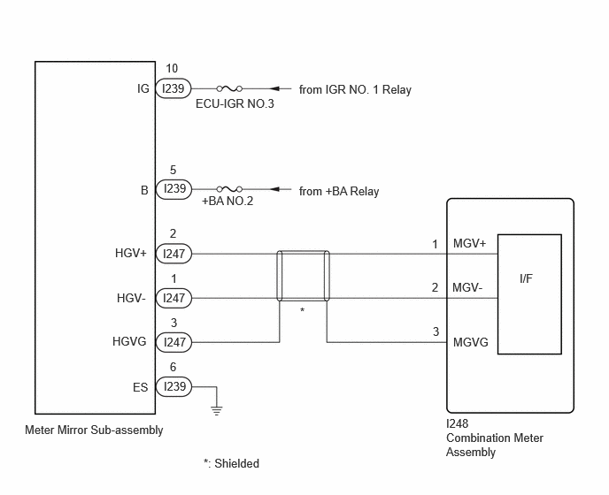
WIRING DIAGRAM
CAUTION / NOTICE / HINT
NOTICE:
- When replacing the combination meter assembly, always replace it with a new one. If a combination meter assembly which was installed to another vehicle is used, the information stored in it will not match the information from the vehicle and a DTC may be stored.
-
When replacing the combination meter assembly, update the ECU security key.
Click here
![2023 - 2025 MY Corolla Corolla Hatchback Corolla HV GR Corolla [09/2022 - ]; SETUP: WHEN REPLACING OR REMOVING/INSTALLING PARTS: UPDATE ECU SECURITY KEY](/t3Portal/stylegraphics/info.gif)
- Inspect the fuses of circuits related to this system before performing the following procedure.
PROCEDURE
|
1. |
CHECK HEADUP DISPLAY |
(a) Turn the settings of the headup display to ON and confirm the startup operation.
Result |
Proceed to |
|---|---|
|
The headup display starts |
A |
|
The headup display does not start |
B |
| B |

|
|

|
2. |
CHECK HARNESS AND CONNECTOR (METER MIRROR SUB-ASSEMBLY - COMBINATION METER ASSEMBLY) |
(a) Disconnect the I247 meter mirror sub-assembly connector.
(b) Disconnect the I248 combination meter assembly connector.
(c) Measure the resistance according to the value(s) in the table below.
Standard Resistance:
|
Tester Connection |
Condition |
Specified Condition |
|---|---|---|
|
I248-1 (MGV+) - I247-2 (HGV+) |
Always |
Below 1 Ω |
|
I248-2 (MGV-) - I247-1 (HGV-) |
Always |
Below 1 Ω |
|
I248-3 (MGVG) - I247-3 (HGVG) |
Always |
Below 1 Ω |
|
I248-1 (MGV+) or I247-2 (HGV+) - Body ground |
Always |
10 kΩ or higher |
|
I248-2 (MGV-) or I247-1 (HGV-) - Body ground |
Always |
10 kΩ or higher |
| NG |
|
REPAIR OR REPLACE HARNESS OR CONNECTOR |
|
|
3. |
REPLACE METER MIRROR SUB-ASSEMBLY |
(a) Replace the meter mirror sub-assembly with a new or known good one.
HINT:
Click here
|
|
4. |
CLEAR DTC |
(a) Clear the DTCs.
Body Electrical > Combination Meter > Clear DTCs
|
|
5. |
CHECK FOR DTC |
(a) Check for DTCs.
Body Electrical > Combination Meter > Trouble Codes
Result |
Proceed to |
|---|---|
|
DTC B151087 is not output |
A |
|
DTC B151087 is output |
B |
| A |
|
END (METER MIRROR SUB-ASSEMBLY IS DEFECTIVE) |
| B |
|
|
6. |
CHECK HARNESS AND CONNECTOR (POWER SOURCE CIRCUIT) |
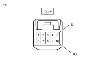
(a) Disconnect the I239 meter mirror sub-assembly connector.
|
(b) Measure the voltage according to the value(s) in the table below. Standard Voltage:
Result:
|
|
| NG |
|
REPAIR OR REPLACE HARNESS OR CONNECTOR |
|
|
7. |
CHECK HARNESS AND CONNECTOR (METER MIRROR SUB-ASSEMBLY - BODY GROUND) |
(a) Measure the resistance according to the value(s) in the table below.
Standard Resistance:
|
Tester Connection |
Condition |
Specified Condition |
|---|---|---|
|
I239-6 (ES)- Body ground |
Always |
Below 1 Ω |
| OK |
|
| NG |
|
REPAIR OR REPLACE HARNESS OR CONNECTOR |
|
|
|