| Last Modified: 01-27-2025 | 6.11:8.1.0 | Doc ID: RM100000002OVW4 |
| Model Year Start: 2025 | Model: Corolla Hatchback | Prod Date Range: [09/2024 - ] |
| Title: M20A-FKS (ENGINE CONTROL): SFI SYSTEM: Starter Signal Circuit; 2025 MY Corolla Corolla Hatchback [09/2024 - ] | ||
|
Starter Signal Circuit |
DESCRIPTION
While the engine is being cranked, current flows from terminal ST1 of the ignition or starter switch assembly*1 or terminal STAR of the certification ECU (smart key ECU assembly)*2 to terminal STA of the ECM (STA signal).
*1: w/o Smart Key System
*2: w/ Smart Key System
WIRING DIAGRAM
Refer to DTC P061512.
Click here
![2025 MY Corolla Corolla Hatchback [09/2024 - ]; M20A-FKS (ENGINE CONTROL): SFI SYSTEM: P061512; Starter Relay Circuit Short to Battery+](/t3Portal/stylegraphics/info.gif)
CAUTION / NOTICE / HINT
NOTICE:
- Inspect the fuses for circuits related to this system before performing the following procedure.
-
After the ignition switch is turned off, there may be a waiting time before disconnecting the negative (-) battery terminal.
Click here
-
When disconnecting and reconnecting the battery.
HINT:
When disconnecting and reconnecting the battery, there is an automatic learning function that completes learning when the respective system is used.
Click here
PROCEDURE
|
1. |
CHECK WHETHER ENGINE CAN BE CRANKED |
(a) Check if the engine can be cranked.
|
Result |
Proceed to |
|---|---|
|
Engine cannot be cranked |
A |
|
Engine can be cranked |
B |
| B |

|
|

|
2. |
READ VALUE USING TECHSTREAM (STARTER SW) |
(a) Connect the Techstream to the DLC3.
(b) Turn the ignition switch to ON.
(c) Turn the Techstream on.
(d) Enter the following menus: Powertrain / Engine / Data List / Starter SW.
Powertrain > Engine > Data List
|
Tester Display |
|---|
|
Starter SW |
(e) Check the value displayed on the Techstream when the ignition switch is turned to the ON and START positions.
OK:
|
Condition |
Techstream Display (Starter SW) |
|---|---|
|
Ignition switch ON |
OFF |
|
Engine started |
ON |
|
Result |
Proceed to |
|---|---|
|
OK |
A |
|
NG (with Smart Key System) |
B |
|
NG (without Smart Key System) |
C |
| B |
|
| C |
|
|
|
3. |
INSPECT ST RELAY |
(a) Inspect the ST relay.
Click here
| NG |
|
REPLACE ST RELAY |
|
|
4. |
INSPECT STARTER ASSEMBLY |
(a) Inspect the starter assembly.
Click here
| NG |
|
|
|
5. |
CHECK HARNESS AND CONNECTOR (ST RELAY - STARTER ASSEMBLY) |
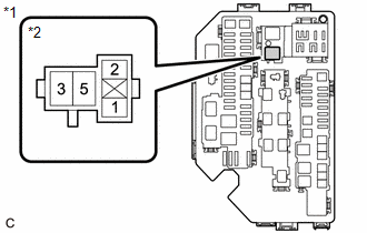
(a) Remove the ST relay from the No. 1 engine room relay block and No. 1 junction block assembly.
(b) Disconnect the starter assembly connector.
(c) Measure the resistance according to the value(s) in the table below.
Standard Resistance:
|
Tester Connection |
Condition |
Specified Condition |
|---|---|---|
|
3 (ST relay) - C82-1 (ST) |
Always |
Below 1 Ω |
|
3 (ST relay) or C82-1 (ST) - Body ground and other terminals |
Always |
10 kΩ or higher |
| NG |
|
REPAIR OR REPLACE HARNESS OR CONNECTOR |
|
|
6. |
CHECK TERMINAL VOLTAGE (BATTERY - STARTER ASSEMBLY) |
(a) Disconnect the cable from the negative (-) battery terminal.
(b) Disconnect the cable from the positive (+) battery terminal.
(c) Disconnect the starter assembly connector.
(d) Measure the resistance according to the value(s) in the table below.
Standard Resistance:
|
Tester Connection |
Condition |
Specified Condition |
|---|---|---|
|
Positive (+) battery terminal - C111-1 (B) |
Always |
Below 1 Ω |
| NG |
|
REPAIR OR REPLACE HARNESS OR CONNECTOR |
|
|
7. |
CHECK TERMINAL VOLTAGE (POWER SOURCE OF ST RELAY) |
|
*1 |
No. 1 Engine Room Relay Block and No. 1 Junction Block Assembly |
|
*2 |
ST Relay |
(a) Remove the ST relay from the No.1 engine room relay block and No.1 junction block assembly.
(b) Measure the voltage according to the value(s) in the table below.
Standard Voltage:
|
Tester Connection |
Condition |
Specified Condition |
|---|---|---|
|
5 (ST relay) - Body ground |
Always |
11 to 14 V |
| NG |
|
REPAIR OR REPLACE HARNESS OR CONNECTOR (BATTERY - ST RELAY) |
|
|
8. |
CHECK HARNESS AND CONNECTOR (ST RELAY - BODY GROUND) |
(a) Remove the ST relay from the No.1 engine room relay block and No.1 junction block assembly.
(b) Measure the resistance according to the value(s) in the table below.
Standard Resistance:
|
Tester Connection |
Condition |
Specified Condition |
|---|---|---|
|
2 (ST relay) - Body ground |
Always |
Below 1 Ω |
| NG |
|
REPAIR OR REPLACE HARNESS OR CONNECTOR |
|
|
9. |
CHECK HARNESS AND CONNECTOR (ST RELAY - ECM) |
(a) Remove the ST relay from the No. 1 engine room relay block and No. 1 junction block assembly.
(b) Disconnect the ECM connector.
(c) Measure the resistance according to the value(s) in the table below.
Standard Resistance:
|
Tester Connection |
Condition |
Specified Condition |
|---|---|---|
|
2 (ST relay holder) - A178-18 (STA) |
Always |
Below 1 Ω |
| OK |
|
PROCEED TO NEXT SUSPECTED AREA SHOWN IN PROBLEM SYMPTOMS TABLE |
| NG |
|
REPAIR OR REPLACE HARNESS OR CONNECTOR |
|
10. |
CHECK HARNESS AND CONNECTOR (STA SIGNAL CIRCUIT) |
(a) Remove the ST relay from the No. 1 engine room relay block and No. 1 junction block assembly.
(b) Disconnect the ECM connector.
(c) Disconnect the certification ECU (smart key ECU assembly) connector.
(d) Measure the resistance according to the value(s) in the table below.
Standard Resistance:
|
Tester Connection |
Condition |
Specified Condition |
|---|---|---|
|
A178-18 (STA) - O175-10 (STAR) |
Always |
Below 1 Ω |
|
A178-18 (STA), O175-10 (STAR) and 1 (ST relay) - Body ground and other terminals |
Always |
10 kΩ or higher |
| OK |
|
| NG |
|
REPAIR OR REPLACE HARNESS OR CONNECTOR |
|
11. |
CHECK HARNESS AND CONNECTOR (N/ST RELAY - ECM - ENGINE STOP AND START ECU) |
(a) Disconnect the ECM connector.
(b) Remove the N/ST relay from the No. 1 engine room relay block and junction block assembly.
(c) Measure the resistance according to the value(s) in the table below.
Standard Resistance:
|
Tester Connection |
Condition |
Specified Condition |
|---|---|---|
|
3 (N/ST relay) - A178-18 (STA) |
Always |
Below 1 Ω |
|
3 (N/ST relay) and A178-18 (STA) - Body ground |
Always |
10 kΩ or higher |
| NG |
|
REPAIR OR REPLACE HARNESS OR CONNECTOR |
|
|
12. |
INSPECT N/ST RELAY |
(a) Inspect the N/ST relay.
Click here
| NG |
|
REPLACE ST NO. 2 RELAY |
|
|
13. |
CHECK TERMINAL VOLTAGE (POWER SOURCE OF N/ST RELAY) |
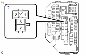
|
*1 |
No. 1 Engine Room Relay Block and Junction Block Assembly |
|
*2 |
N/ST Relay |
(a) Remove the N/ST relay from the No. 1 engine room relay block and junction block assembly.
(b) Measure the voltage according to the value(s) in the table below.
Standard Voltage:
|
Tester Connection |
Condition |
Specified Condition |
|---|---|---|
|
5 (N/ST relay) - Body ground |
Engine started |
11 to 14 V |
| NG |
|
|
|
14. |
CHECK HARNESS AND CONNECTOR (ECM - N/ST RELAY) |
(a) Disconnect the ECM connector.
(b) Remove the N/ST relay from the No. 1 engine room relay block and junction block assembly.
(c) Measure the resistance according to the value(s) in the table below.
Standard Resistance:
|
Tester Connection |
Condition |
Specified Condition |
|---|---|---|
|
C160-32 (NSR+) - 2 (N/ST relay) |
Always |
Below 1 Ω |
|
C160-33 (NSR-) - 1 (N/ST relay) |
Always |
Below 1 Ω |
|
C160-32 (NSR+) or 2 (N/ST relay) - Body ground and other terminals |
Always |
10 kΩ or higher |
|
C160-33 (NSR-) or 1 (N/ST relay) - Body ground and other terminals |
Always |
10 kΩ or higher |
| OK |
|
| NG |
|
REPAIR OR REPLACE HARNESS OR CONNECTOR |
|
15. |
CHECK HARNESS AND CONNECTOR (IGNITION SWITCH ASSEMBLY - N/ST RELAY) |
(a) Disconnect the ignition switch assembly connector.
(b) Remove the N/ST relay from the No. 1 engine room relay block and junction block assembly.
(c) Measure the resistance according to the value(s) in the table below.
Standard Resistance:
|
Tester Connection |
Condition |
Specified Condition |
|---|---|---|
|
I12-5 (ST1) - 5 (N/ST relay) |
Always |
Below 1 Ω |
|
I12-5 (ST1) or 5 (N/ST relay) - Body ground |
Always |
10 kΩ or higher |
| NG |
|
REPAIR OR REPLACE HARNESS OR CONNECTOR |
|
|
16. |
INSPECT IGNITION SWITCH ASSEMBLY |
(a) Inspect the ignition switch assembly.
Click here
| OK |
|
REPAIR OR REPLACE HARNESS OR CONNECTOR (BATTERY - IGNITION SWITCH ASSEMBLY) |
| NG |
|
|
17. |
READ VALUE USING TECHSTREAM (STARTER SW) |
(a) Connect the Techstream to the DLC3.
(b) Turn the ignition switch to ON.
(c) Turn the Techstream on.
(d) Enter the following menus: Powertrain / Engine / Data List / Starter SW.
Powertrain > Engine > Data List
|
Tester Display |
|---|
|
Starter SW |
(e) Check the value displayed on the Techstream when the ignition switch is turned to the ON and START positions.
OK:
|
Condition |
Techstream Display (Starter SW) |
|---|---|
|
Ignition switch ON |
OFF |
|
Engine started |
ON |
| OK |
|
PROCEED TO NEXT SUSPECTED AREA SHOWN IN PROBLEM SYMPTOMS TABLE |
| NG |
|
REPAIR OR REPLACE HARNESS OR CONNECTOR (ST RELAY - ECM) |
|
|
|