- Wireless Door Lock Control System (for Gasoline Model with Smart Key System)
- Smart Key System (for Gasoline Model, Entry Function)
- Smart Key System (for Gasoline Model, Start Function)
- Steering lock function*1
| Last Modified: 01-27-2025 | 6.11:8.1.0 | Doc ID: RM100000002OT8D |
| Model Year Start: 2025 | Model: GR Corolla | Prod Date Range: [09/2024 - ] |
| Title: UC80F (AUTOMATIC TRANSMISSION / TRANSAXLE): AUTOMATIC TRANSAXLE ASSEMBLY: REMOVAL; 2025 MY Corolla Corolla Hatchback GR Corolla [09/2024 - ] | ||
REMOVAL
CAUTION / NOTICE / HINT
The necessary procedures (adjustment, calibration, initialization or registration) that must be performed after parts are removed and installed, or replaced during automatic transaxle assembly removal/installation are shown below.
Necessary Procedure After Parts Removed/Installed/Replaced
|
Replaced Part or Performed Procedure |
Necessary Procedure |
Effect/Inoperative Function when Necessary Procedure not Performed |
Link |
|---|---|---|---|
|
*1:w/ Steering Lock Function
*2: Not necessary when ECM replaced with new one. *3: If transaxle compensation code read from ECM *4: If transaxle compensation code not read from ECM |
|||
|
Replacement of ECM |
Vehicle Identification Number (VIN) registration |
MIL comes on |
|
|
ECU configuration |
- |
|
|
|
Update ECU security key |
Vehicle Control History (RoB) are stored |
|
|
|
Heavy Knock History |
- |
|
|
|
ECU communication ID registration (Immobiliser system) |
Engine start function |
|
|
|
Code registration (Smart Key System (for Gasoline Model, Start Function)) |
|
|
|
|
|
Initialization:
Registration:
|
|
|
Inspection after repair |
|
|
|
Automatic transaxle assembly |
|
|
Initialization:
Registration:
|
|
Automatic transaxle fluid |
ATF thermal degradation estimate reset |
The value of the Data List item "ATF Thermal Degradation Estimate" is not estimated correctly |
|
|
Front wheel alignment adjustment |
|
|
|
|
Tire |
ECU Data Initialization (When performing tire replacement after RoB code X2104 is output) |
Active Torque Split AWD System |
|
CAUTION:
-
The engine assembly with transaxle is very heavy. Be sure to follow the procedure described in the repair manual, or the engine lifter may suddenly drop or the engine assembly with transaxle may fall off the engine lifter.
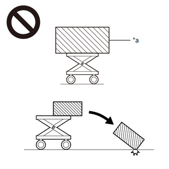
*a
An Object Exceeding Weight Limit of Engine Lifter
-
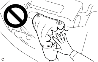
To prevent burns, do not touch the engine, exhaust manifold or other high temperature components while the engine is hot.
-
The automatic transaxle assembly is very heavy. Be sure to follow the procedure described in the repair manual, or the transmission jack may suddenly drop.
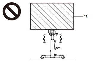
*a
An Object Exceeding Weight Limit of Transmission Jack
NOTICE:
If automatic transaxle assembly parts are replaced, refer to Parts Replacement Compensation Table to determine if any additional operations are necessary.
Click here
![2025 MY Corolla Corolla Hatchback GR Corolla [09/2024 - ]; UC80F (AUTOMATIC TRANSMISSION / TRANSAXLE): AUTOMATIC TRANSAXLE SYSTEM: PRECAUTION](/t3Portal/stylegraphics/info.gif)
HINT:
When the cable is disconnected / reconnected to the auxiliary battery terminal, systems temporarily stop operating. However, each system has a function that completes learning the first time the system is used.
-
Learning completes when vehicle is driven
Effect/Inoperative Function When Necessary Procedures are not Performed
Necessary Procedures
Link
Front Camera System
Drive the vehicle straight ahead at 35 km/h (22 mph) or more for 5 seconds or more.
-
Learning completes when vehicle is operated normally
Effect/Inoperative Function When Necessary Procedures are not Performed
Necessary Procedures
Link
Power door lock control system
- Back door opener
Perform door unlock operation with door control switch or electrical key transmitter sub-assembly switch.
PROCEDURE
1. REMOVE ENGINE ASSEMBLY WITH TRANSAXLE
Click here
2. DISCONNECT WIRE HARNESS
|
(a) Disconnect the air fuel ratio sensor connector. |
|
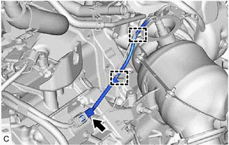
(b) Disengage the 2 clamps.
3. REMOVE EXHAUST MANIFOLD CONVERTER SUB-ASSEMBLY
Click here
4. REMOVE EXHAUST PIPE CLAMP
Click here
5. REMOVE OUTLET TURBINE ELBOW GASKET
Click here
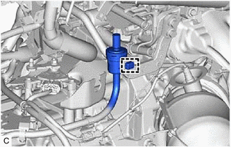
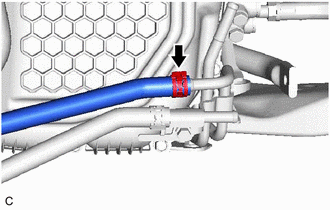
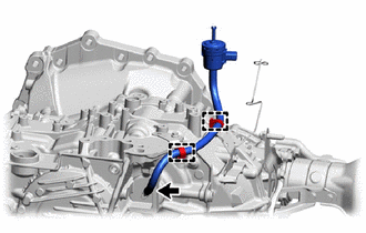
6. DISCONNECT TRANSMISSION BREATHER HOSE SUB-ASSEMBLY
|
(a) Disengage the clamp to disconnect the transmission breather hose sub-assembly from the flexible hose bracket. |
|
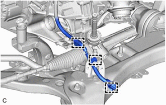
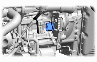
7. SEPARATE ENGINE WIRE
|
(a) Disengage the clamp and guide. |
|
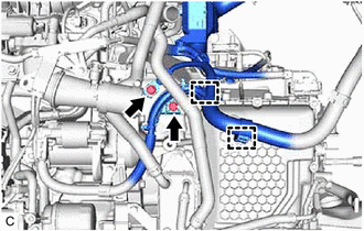
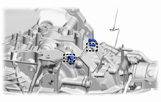
(b) Remove the 2 bolts.
|
(c) Disengage the 3 clamps. |
|
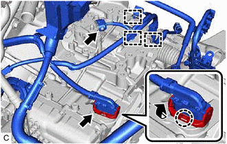
(d) Disengage the claw, rotate the lever and disconnect the transmission wire connector.
(e) Disconnect the park/neutral position switch assembly connector.
|
(f) Disengage the clamp to disconnect the No. 1 fuel vapor feed hose. |
|
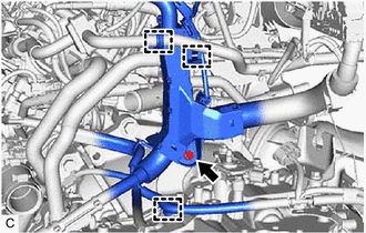
(g) Remove the bolt.
(h) Disengage the 2 clamps.
|
(i) Disengage the 3 clamps. |
|
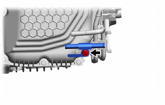
8. DISCONNECT OUTLET NO. 1 OIL COOLER HOSE
|
(a) Slide the clip and disconnect the outlet No. 1 oil cooler hose from the oil cooler union sub-assembly. HINT: Use a container to catch any automatic transaxle fluid which flows out. |
|
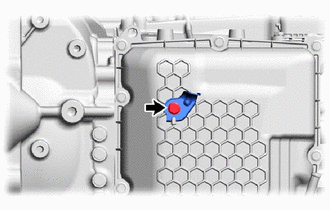
9. DISCONNECT NO. 1 TRANSMISSION OIL COOLER HOSE
|
(a) Slide the clip and disconnect the No. 1 transmission oil cooler hose from the No. 1 oil cooler tube sub-assembly without hose. HINT: Use a container to catch any automatic transaxle fluid which flows out. |
|
10. DISCONNECT NO. 4 WATER BY-PASS HOSE
Click here
11. DISCONNECT NO. 5 WATER BY-PASS HOSE
Click here
12. REMOVE TRANSMISSION OIL COOLER
Click here
13. REMOVE NO. 2 TRANSMISSION OIL COOLER BRACKET
|
(a) Remove the 3 bolts and No. 2 transmission oil cooler bracket from the transaxle housing. |
|
14. REMOVE FLYWHEEL HOUSING SIDE COVER
Click here
15. REMOVE STARTER ASSEMBLY
Click here
16. REMOVE FLYWHEEL HOUSING UNDER COVER
|
(a) Remove the flywheel housing under cover from the cylinder block sub-assembly. |
|
17. REMOVE DRIVE PLATE AND TORQUE CONVERTER ASSEMBLY SETTING BOLT
|
(a) Turn the crankshaft to gain access to the 6 drive plate and torque converter assembly setting bolts and remove each drive plate and torque converter assembly setting bolt while holding the crankshaft pulley set bolt with a wrench. HINT: There will be one black colored drive plate and torque converter assembly setting bolt. |
|
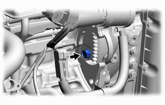
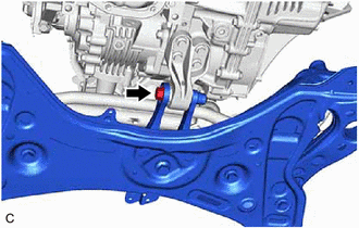
18. REMOVE FRONT SUSPENSION CROSSMEMBER SUB-ASSEMBLY
|
(a) Remove the bolt and front suspension crossmember sub-assembly from the No. 2 engine moving control rod. |
|
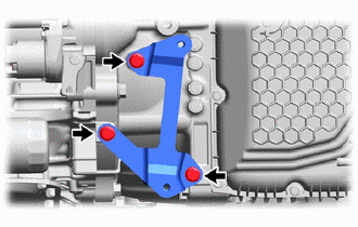
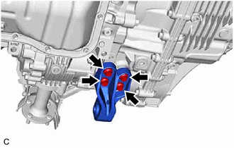
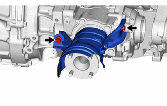
19. REMOVE NO. 2 ENGINE MOVING CONTROL ROD
|
(a) Remove the 4 bolts and No. 2 engine moving control rod from the transaxle housing. |
|
20. REMOVE PROPELLER SHAFT HEAT INSULATOR
|
(a) Remove the 2 bolts and propeller shaft heat insulator from the transfer assembly. |
|
21. REMOVE AUTOMATIC TRANSAXLE ASSEMBLY
|
(a) Support the automatic transaxle assembly with a transmission jack. NOTICE: Secure the automatic transaxle assembly to the transmission jack using a suitable adapter, such as a rope or attachment. |
|
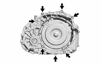
(b) Remove the 7 bolts and automatic transaxle assembly from the engine assembly.
NOTICE:
To prevent damage to the 2 knock pins, do not pry between the automatic transaxle assembly and engine assembly.
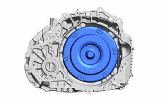
22. REMOVE TORQUE CONVERTER ASSEMBLY
|
(a) Remove the torque converter assembly from the automatic transaxle assembly. |
|
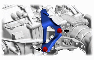
23. REMOVE EXHAUST PIPE SUPPORT STAY
|
(a) Remove the 2 bolts and exhaust pipe support stay from the transaxle housing. |
|
24. REMOVE TRANSFER ASSEMBLY
Click here
25. REMOVE NO. 1 OIL COOLER TUBE SUB-ASSEMBLY WITHOUT HOSE
|
(a) Remove the bolt and No. 1 oil cooler tube sub-assembly without hose from the oil cooler union sub-assembly. |
|
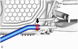
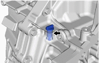
26. REMOVE TRANSMISSION BREATHER HOSE SUB-ASSEMBLY
|
(a) Using a screwdriver with its tip wrapped with protective tape, remove the transmission breather hose sub-assembly from the No. 1 breather plug (ATM). NOTICE: Be careful not to damage the No. 1 breather plug (ATM). |
|
(b) Disengage the 2 clamps.
27. REMOVE WIRING HARNESS CLAMP
|
(a) Disengage the 2 clamps to remove the 2 wiring harness clamps from the automatic transaxle case sub-assembly. |
|
28. REMOVE WIRE HARNESS CLAMP BRACKET
|
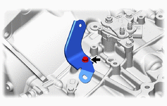
(a) Remove the bolt and wire harness clamp bracket from the transmission case side cover. |
|
|
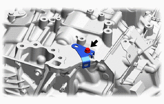
(b) Remove the bolt and wire harness clamp bracket from the automatic transaxle case sub-assembly. |
|
|
(c) Remove the bolt and wire harness clamp bracket from the automatic transaxle case sub-assembly. |
|
29. REMOVE EXHAUST SENSOR CLAMP BRACKET
|
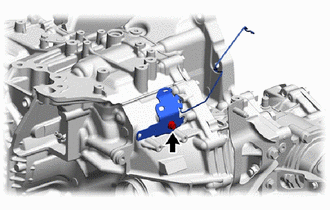
(a) Remove the bolt and exhaust sensor clamp bracket from the automatic transaxle case sub-assembly. |
|
30. REMOVE NO. 1 TRANSMISSION CONTROL CABLE BRACKET
|
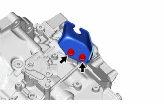
(a) Remove the 2 bolts and No. 1 transmission control cable bracket from the automatic transaxle case sub-assembly. |
|
31. REMOVE TRANSMISSION CASE PLUG ASSEMBLY
|
(a) Remove the transmission case plug assembly from the transaxle housing. |
|
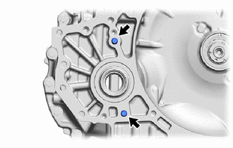
32. REMOVE TRANSFER AND TRANSAXLE SETTING STUD BOLT
|
(a) Type A: (1) Using 2 nuts, remove the 2 transfer and transaxle setting stud bolts from the automatic transaxle assembly. |
|
|
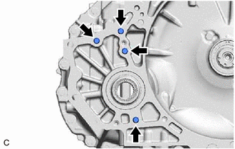
(b) Type B: (1) Using 2 nuts, remove the 4 transfer and transaxle setting stud bolts from the automatic transaxle assembly. |
|
33. INSPECT TORQUE CONVERTER ASSEMBLY
Click here
34. INSPECT DRIVE PLATE AND RING GEAR SUB-ASSEMBLY
Click here
|
|
|