| Last Modified: 01-27-2025 | 6.11:8.1.0 | Doc ID: RM100000002OT8B |
| Model Year Start: 2025 | Model: GR Corolla | Prod Date Range: [09/2024 - ] |
| Title: UC80F (AUTOMATIC TRANSMISSION / TRANSAXLE): AUTOMATIC TRANSAXLE ASSEMBLY: INSTALLATION; 2025 MY Corolla Corolla Hatchback GR Corolla [09/2024 - ] | ||
INSTALLATION
CAUTION / NOTICE / HINT
CAUTION:
The engine assembly with transaxle is very heavy. Be sure to follow the procedure described in the repair manual, or the engine lifter may suddenly drop or the engine assembly with transaxle may fall off the engine lifter.
PROCEDURE
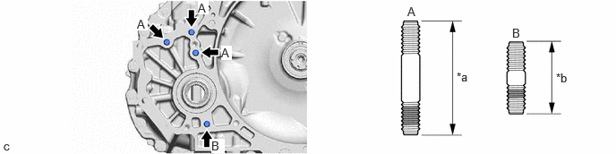
1. INSTALL TRANSFER AND TRANSAXLE SETTING STUD BOLT
(a) Clean the transfer and transaxle setting stud bolt holes.
(b) Using 2 nuts, install 4 new transfer and transaxle setting stud bolts to the automatic transaxle assembly at the positions shown in the illustration.
|
*a |
73 mm (2.87 in.) |
*b |
53 mm (2.09 in.) |

|
Sealed Portion |
- |
- |
Torque:
39.2 N·m {400 kgf·cm, 29 ft·lbf}
NOTICE:
Install the sealed side of the transfer and transaxle setting stud bolt to the automatic transaxle assembly.
2. INSTALL TRANSMISSION CASE PLUG ASSEMBLY
(a) Coat the O-ring of a new transmission case plug assembly with Toyota Genuine ATF WS.
(b) Install the transmission case plug assembly to the transaxle housing.
3. INSTALL NO. 1 TRANSMISSION CONTROL CABLE BRACKET
(a) Install the No. 1 transmission control cable bracket to the automatic transaxle case sub-assembly with the 2 bolts.
Torque:
12 N·m {122 kgf·cm, 9 ft·lbf}
4. INSTALL EXHAUST SENSOR CLAMP BRACKET
(a) Install the exhaust sensor clamp bracket to the automatic transaxle case sub-assembly with the bolt.
Torque:
21 N·m {214 kgf·cm, 15 ft·lbf}
5. INSTALL WIRE HARNESS CLAMP BRACKET
(a) Install the wire harness clamp bracket to the automatic transaxle case sub-assembly with the bolt.
Torque:
10 N·m {102 kgf·cm, 7 ft·lbf}
(b) Install the wire harness clamp bracket to the automatic transaxle case sub-assembly with the bolt.
Torque:
10 N·m {102 kgf·cm, 7 ft·lbf}
(c) Install the wire harness clamp bracket to the transmission case side cover with the bolt.
Torque:
10 N·m {102 kgf·cm, 7 ft·lbf}
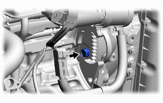
6. INSTALL WIRING HARNESS CLAMP
(a) Engage the 2 clamps to install the 2 wiring harness clamps to the automatic transaxle case sub-assembly.
7. INSTALL TRANSMISSION BREATHER HOSE SUB-ASSEMBLY
(a) Engage the 2 clamps.
(b) Install the transmission breather hose sub-assembly to the No. 1 breather plug (ATM).
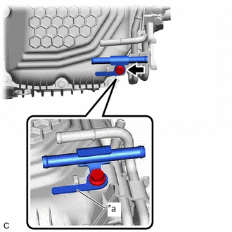
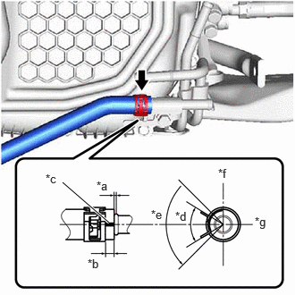
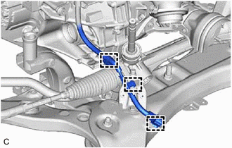
8. INSTALL NO. 1 OIL COOLER TUBE SUB-ASSEMBLY WITHOUT HOSE
|
(a) Install the No. 1 oil cooler tube sub-assembly without hose to the oil cooler union sub-assembly with the bolt. Torque: 5.5 N·m {56 kgf·cm, 49 in·lbf} NOTICE: Align the stopper on the No. 1 oil cooler tube sub-assembly without hose as shown in the illustration. |
|
9. INSTALL TRANSFER ASSEMBLY
Click here
![2025 MY Corolla Corolla Hatchback GR Corolla [09/2024 - ]; GF1A (TRANSFER / 4WD / AWD): TRANSFER ASSEMBLY: INSTALLATION+](/t3Portal/stylegraphics/info.gif)
10. INSTALL EXHAUST PIPE SUPPORT STAY
(a) Install the exhaust pipe support stay to the transaxle housing with the 2 bolts.
Torque:
43 N·m {438 kgf·cm, 32 ft·lbf}
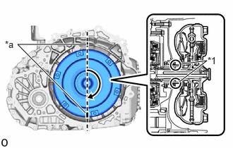
11. INSTALL TORQUE CONVERTER ASSEMBLY
|
(a) Set the key at the top of the front oil pump drive gear and put a matchmark on the transaxle housing. |
|
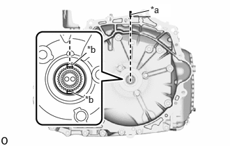
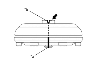
(b) Apply MP grease to place a matchmark on the torque converter assembly so that the position of its groove is clearly indicated.
|
*a |
Matchmark |
|
*b |
Groove |

|
MP Grease |
|
(c) Align the matchmark on the transaxle housing with the one on the torque converter assembly and engage the splines of the input shaft with the turbine runner splines. NOTICE:
|
|

|
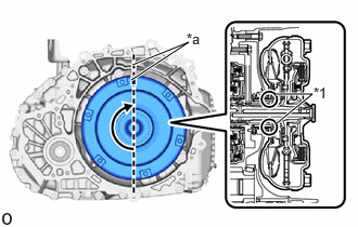
(d) Rotate the torque converter assembly approximately 180° and engage the splines of the stator shaft with the stator assembly. NOTICE:
|
|
|
(e) Rotate the torque converter assembly approximately 180° again, align the matchmark on the torque converter assembly with the one on the transaxle housing and insert the groove of the torque converter assembly into the key of the front oil pump drive gear. NOTICE:
|
|
|
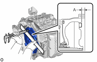
(f) Using a vernier caliper and straightedge, measure the dimension (A) shown in the illustration and check the dimension (A). Standard: 14 mm (0.5512 in.) or more NOTICE:
|
|
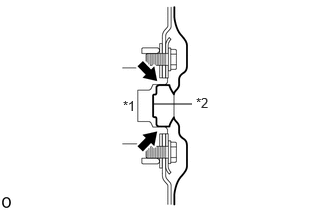
12. INSTALL AUTOMATIC TRANSAXLE ASSEMBLY
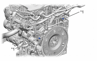
(a) Apply clutch spline grease to the surface of the crankshaft that contacts the torque converter assembly centerpiece.
Clutch Spline Grease:
Toyota Genuine Clutch Spline Grease or equivalent
Maximum Grease Amount:
Approximately 1 g (0.0353 oz)
|
*1 |
Crankshaft |
|
*2 |
Torque Converter Assembly Centerpiece |
|
|
Clutch Spline Grease |
|
(b) Confirm that the 2 knock pins are installed on the engine assembly and are not damaged. |
|
|
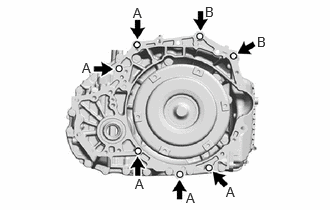
(c) While keeping the engine assembly and automatic transaxle assembly horizontal, align the 2 knock pins with the holes in the automatic transaxle assembly and install the automatic transaxle assembly with the 7 bolts shown in the illustration. Torque: Bolt (A) : 46 N·m {469 kgf·cm, 34 ft·lbf} Bolt (B) : 64 N·m {653 kgf·cm, 47 ft·lbf} Bolt Length:
NOTICE:
|
|
13. INSTALL PROPELLER SHAFT HEAT INSULATOR
|
(a) Install the propeller shaft heat insulator to the transfer assembly with the 2 bolts in the order shown in the illustration. Torque: 25 N·m {255 kgf·cm, 18 ft·lbf} |
|
14. INSTALL NO. 2 ENGINE MOVING CONTROL ROD
|
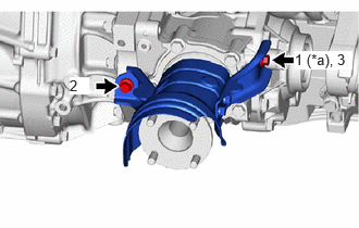
(a) Install the No. 2 engine moving control rod to the transaxle housing with the 4 bolts in the order shown in the illustration. Torque: 44 N·m {449 kgf·cm, 32 ft·lbf} |
|
15. INSTALL FRONT SUSPENSION CROSSMEMBER SUB-ASSEMBLY
(a) Install the front suspension crossmember sub-assembly to the No. 2 engine moving control rod with the bolt.
Torque:
170 N·m {1734 kgf·cm, 125 ft·lbf}
16. INSTALL DRIVE PLATE AND TORQUE CONVERTER ASSEMBLY SETTING BOLT
|
(a) Turn the crankshaft to gain access to the installation locations of the 6 drive plate and torque converter assembly setting bolts and install each drive plate and torque converter assembly setting bolt while holding the crankshaft pulley set bolt with a wrench. Torque: 69 N·m {704 kgf·cm, 51 ft·lbf} NOTICE: First install the black colored drive plate and torque converter assembly setting bolt, and then the remaining 5 silver colored drive plate and torque converter assembly setting bolts. |
|
17. INSTALL FLYWHEEL HOUSING UNDER COVER
(a) Install the flywheel housing under cover to the cylinder block sub-assembly.
18. INSTALL STARTER ASSEMBLY
Click here
19. INSTALL FLYWHEEL HOUSING SIDE COVER
Click here
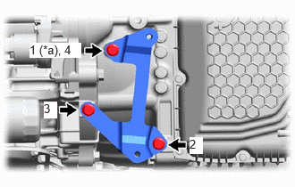
20. INSTALL NO. 2 TRANSMISSION OIL COOLER BRACKET
|
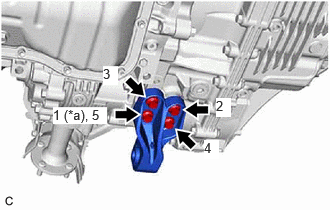
(a) Install the No. 2 transmission oil cooler bracket to the transaxle housing with the 3 bolts in the order shown in the illustration. Torque: 13.5 N·m {138 kgf·cm, 10 ft·lbf} |
|
21. INSTALL TRANSMISSION OIL COOLER
Click here
22. CONNECT NO. 5 WATER BY-PASS HOSE
Click here
23. CONNECT NO. 4 WATER BY-PASS HOSE
Click here
24. CONNECT NO. 1 TRANSMISSION OIL COOLER HOSE
|
(a) Connect the No. 1 transmission oil cooler hose to the No. 1 oil cooler tube sub-assembly without hose and slide the clip to secure it. NOTICE:
|
|
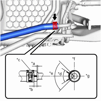
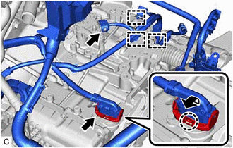
25. CONNECT OUTLET NO. 1 OIL COOLER HOSE
|
(a) Connect the outlet No. 1 oil cooler hose to the oil cooler union sub-assembly and slide the clip to secure it. NOTICE:
|
|
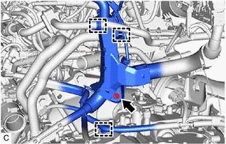
26. INSTALL ENGINE WIRE
|
(a) Engage the 3 clamps. |
|
|
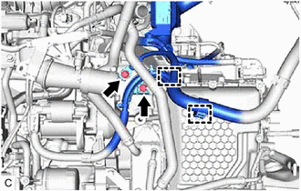
(b) Engage the 2 clamps. |
|
(c) Install the bolt.
Torque:
10 N·m {102 kgf·cm, 7 ft·lbf}
(d) Engage the clamp to connect the No. 1 fuel vapor feed hose.
|
(e) Connect the park/neutral position switch assembly connector. |
|
(f) Connect the transmission wire connector and rotate the lever to engage the claw.
HINT:
Rotate the lever until the claw of the transmission wire connector makes a click sound.
(g) Engage the 3 clamps.
|
(h) Install the 2 bolts. Torque: 20 N·m {204 kgf·cm, 15 ft·lbf} |
|
(i) Engage the guide and clamp.
27. CONNECT TRANSMISSION BREATHER HOSE SUB-ASSEMBLY
(a) Engage the clamp to connect the transmission breather hose sub-assembly to the flexible hose bracket.
28. INSTALL OUTLET TURBINE ELBOW GASKET
Click here
29. INSTALL EXHAUST PIPE CLAMP
Click here
30. INSTALL EXHAUST MANIFOLD CONVERTER SUB-ASSEMBLY
Click here
31. CONNECT WIRE HARNESS
(a) Engage the 2 clamps.
(b) Connect the air fuel ratio sensor connector.
32. INSTALL ENGINE ASSEMBLY WITH TRANSAXLE
Click here
33. CHECK AUTOMATIC TRANSAXLE SYSTEM
NOTICE:
If automatic transaxle assembly parts are replaced, refer to Parts Replacement Compensation Table to determine if any additional operations are necessary.
Click here
|
|
|