- DTC judgment completed
- System normal
| Last Modified: 01-27-2025 | 6.11:8.1.0 | Doc ID: RM100000002OT6O |
| Model Year Start: 2025 | Model: GR Corolla | Prod Date Range: [09/2024 - ] |
| Title: UC80F (AUTOMATIC TRANSMISSION / TRANSAXLE): AUTOMATIC TRANSAXLE SYSTEM: P170300; AT Solenoid Output Malfunction; 2025 MY Corolla Corolla Hatchback GR Corolla [09/2024 - ] | ||
|
DTC |
P170300 |
AT Solenoid Output Malfunction |
DESCRIPTION
The ECM detects an erroneous downshift output to the automatic transmission or a gear shifting malfunction.
|
DTC No. |
Detection Item |
DTC Detection Condition |
Trouble Area |
MIL |
Note |
|---|---|---|---|---|---|
|
P170300 |
AT Solenoid Output Malfunction |
ECM internal malfunction (1-trip detection logic) |
|
Comes on |
SAE Code: P1703 |
MONITOR DESCRIPTION
When an erroneous downshift is output or a gear shifting malfunction is detected while downshifting or changing gears while driving, the ECM stores a DTC.
MONITOR STRATEGY
|
Related DTCs |
P1703: Incorrect shift solenoid performance |
|
Required sensors/Components |
Transmission revolution sensor (NC) Solenoid (SL1) valve Solenoid (SL2) valve Solenoid (SL3) valve Solenoid (SL4) valve Solenoid (SL5) valve Solenoid (SL6) valve Solenoid (SL) valve Solenoid (SLU) valve |
|
Frequency of operation |
Continuous |
|
Duration |
0.1 sec. |
|
MIL operation |
1 driving cycle |
|
Sequence of operation |
None |
TYPICAL ENABLING CONDITIONS
Condition (B) and (C)
|
Output speed |
10000 rpm or more |
Condition (D), (E) and (F)
|
Output speed |
5390 rpm or more |
Condition (G), (H), (I) and (J)
|
Output speed |
More than 1198 rpm |
TYPICAL MALFUNCTION THRESHOLDS
Condition (A)
|
Target gear is low (less than allowed gears) |
- |
|
Target gear is 1st or 2nd or 3rd or 4th or 5th gear |
- |
Condition (B)
|
Target gear |
More than -10 |
|
Actual gear |
5th |
Condition (C)
|
Target gear |
More than -10 |
|
Actual gear |
4th |
Condition (D)
|
Target gear |
More than 5 |
|
Actual gear |
3rd |
Condition (E)
|
Target gear |
More than 2 |
|
Actual gear |
2nd |
Condition (F)
|
Target gear |
More than 1 |
|
Actual gear |
1st |
Condition (G)
|
Shift position |
D |
|
Current of SL1 |
ON |
|
Current of SL2 |
ON |
|
Current of SL3 |
ON |
Condition (H)
|
Shift position |
D |
|
Current of SL1 |
ON |
|
Current of SL2 |
ON |
|
Current of SL4 |
ON |
Condition (I)
|
Shift position |
D |
|
Current of SL1 |
ON |
|
Current of SL3 |
ON |
|
Current of SL4 |
ON |
Condition (J)
|
Shift position |
D |
|
Current of SL2 |
ON |
|
Current of SL3 |
ON |
|
Current of SL4 |
ON |
CONFIRMATION DRIVING PATTERN
HINT:
- After repairs have been completed, clear the DTCs and then check that the vehicle has returned to normal by performing the following All Readiness check procedure.
-
When clearing the permanent DTCs, refer to the Clear Permanent DTC procedure.
Click here
![2025 MY Corolla Corolla Hatchback GR Corolla [09/2024 - ]; UC80F (AUTOMATIC TRANSMISSION / TRANSAXLE): AUTOMATIC TRANSAXLE SYSTEM: DTC CHECK / CLEAR](/t3Portal/stylegraphics/info.gif)
- Clear the DTCs (even if no DTCs are stored, perform the clear DTC procedure).
- Turn the ignition switch off and wait for 2 minutes or more.
- Turn the ignition switch to ON and turn the GTS on.
- Start the engine.
-
Perform the D Position Shift Test inspection in Road Test. [*1]
Click here
HINT:
[*1]: Normal judgment procedure.
The normal judgment procedure is used to complete DTC judgment and also used when clearing permanent DTCs.
- Enter the following menus: Powertrain / Transmission / Utility / All Readiness.
- Input the DTC: P170300.
-
Check the DTC judgment result.
GTS Display
Description
NORMAL
ABNORMAL
- DTC judgment completed
- System abnormal
INCOMPLETE
- DTC judgment not completed
- Perform driving pattern after confirming DTC enabling conditions
N/A
- Unable to perform DTC judgment
- Number of DTCs which do not fulfill DTC preconditions has reached ECU memory limit
HINT:
- If the judgment result shows NORMAL, the system is normal.
- If the judgment result shows ABNORMAL, the system has a malfunction.
- If the judgment result shows INCOMPLETE or N/A, perform the normal judgment procedure again.
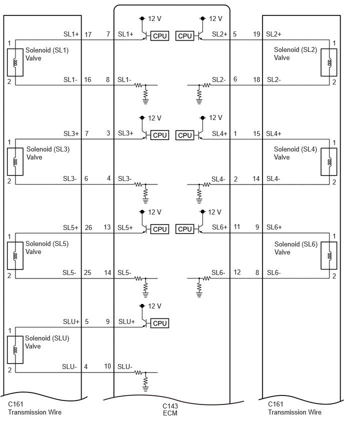
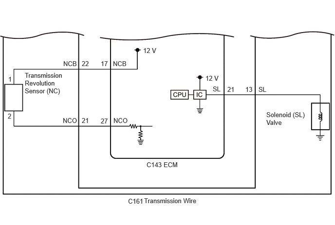
WIRING DIAGRAM
CAUTION / NOTICE / HINT
NOTICE:
-
Perform the universal trip to clear permanent DTCs.
Click here
-
Perform registration and/or initialization when parts related to the automatic transaxle are replaced.
Click here
PROCEDURE
|
1. |
CHECK HARNESS AND CONNECTOR (TRANSMISSION WIRE (SOLENOID VALVE) - ECM) |
(a) Disconnect the C143 ECM connector.
(b) Measure the resistance according to the value (s) in the table below.
Standard Resistance:
|
Tester Connection |
Condition |
Specified Condition |
|---|---|---|
|
C143-7 (SL1+) - C143-8 (SL1-) |
20°C (68°F) |
5.0 to 5.6 Ω |
|
C143-5 (SL2+) - C143-6 (SL2-) |
20°C (68°F) |
5.0 to 5.6 Ω |
|
C143-3 (SL3+) - C143-4 (SL3-) |
20°C (68°F) |
5.0 to 5.6 Ω |
|
C143-1 (SL4+) - C143-2 (SL4-) |
20°C (68°F) |
5.0 to 5.6 Ω |
|
C143-13 (SL5+) - C143-14 (SL5-) |
20°C (68°F) |
5.0 to 5.6 Ω |
|
C143-11 (SL6+) - C143-12 (SL6-) |
20°C (68°F) |
5.0 to 5.6 Ω |
|
C143-9 (SLU+) - C143-10 (SLU-) |
20°C (68°F) |
5.0 to 5.6 Ω |
|
C143-21 (SL) - Body ground |
20°C (68°F) |
11 to 15 Ω |
|
C143-7 (SL1+) or C143-8 (SL1-) - Body ground and other terminals |
Always |
10 kΩ or higher |
|
C143-5 (SL2+) or C143-6 (SL2-) - Body ground and other terminals |
Always |
10 kΩ or higher |
|
C143-3 (SL3+) or C143-4 (SL3-) - Body ground and other terminals |
Always |
10 kΩ or higher |
|
C143-1 (SL4+) or C143-2 (SL4-) - Body ground and other terminals |
Always |
10 kΩ or higher |
|
C143-13 (SL5+) or C143-14 (SL5-) - Body ground and other terminals |
Always |
10 kΩ or higher |
|
C143-11 (SL6+) or C143-12 (SL6-) - Body ground and other terminals |
Always |
10 kΩ or higher |
|
C143-9 (SLU+) or C143-10 (SLU-) - Body ground and other terminals |
Always |
10 kΩ or higher |
| NG |

|
|

|
2. |
READ VALUE USING GTS (NC SENSOR SPEED AND NC SENSOR VOLTAGE) |
(a) Read the Data List according to the display on the GTS.
Powertrain > Transmission > Data List
|
Tester Display |
Measurement Item |
Range |
Normal Condition |
Diagnostic Note |
|---|---|---|---|---|
|
NC Sensor Speed |
Counter gear speed |
Min.: 0 rpm Max.: 12750 rpm |
- |
- |
|
NC Sensor Voltage |
NC sensor voltage |
Min.: 0.000 V Max.: 4.999 V |
0.1 to 1.9 V: Engine idling |
- |
Powertrain > Transmission > Data List
|
Tester Display |
|---|
|
NC Sensor Speed |
|
NC Sensor Voltage |
|
Result |
Proceed to |
|---|---|
|
Data List values are normal |
A |
|
Data List values are not normal |
B |
| B |
|
|
|
3. |
CLEAR DTC |
(a) Clear the DTCs.
Powertrain > Transmission > Clear DTCs
(b) Turn the ignition switch off and wait for 30 seconds or more.
|
|
4. |
READ OUTPUT DTC |
(a) Perform the D Position Shift Test inspection in Road Test.
Click here
(b) Read the DTCs using the GTS.
Powertrain > Transmission > Trouble Codes
|
Result |
Proceed to |
|---|---|
|
DTCs are not output |
A |
|
DTC P170300 is output |
B |
| A |
|
END |
|
|
5. |
REPLACE ECM |
Click here
| NEXT |
|
|
6. |
INSPECT TRANSMISSION REVOLUTION SENSOR (NC) (NC TERMINAL) |
|
(a) Disconnect the C161 transmission wire connector. |
|
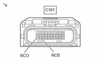
(b) Measure the resistance according to the value(s) in the table below.
Standard Resistance:
|
Tester Connection |
Condition |
Specified Condition |
|---|---|---|
|
C161-21 (NCO) - Body ground |
Always |
99 to 101 Ω |
(c) Turn the ignition switch to ON.
(d) Measure the voltage according to the value(s) in the table below.
Standard Voltage:
|
Tester Connection |
Switch Condition |
Specified Condition |
|---|---|---|
|
C161-22 (NCB) - Body ground |
Ignition switch ON |
11 to 14 V |
| NG |
|
|
|
7. |
INSPECT TRANSMISSION WIRE (TRANSMISSION REVOLUTION SENSOR (NC)) |
|
(a) Disconnect the transmission revolution sensor (NC) connector.
Click here
|
|
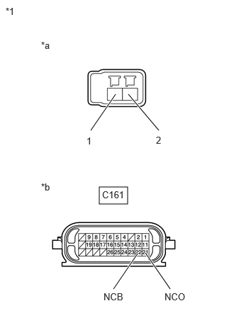
(b) Disconnect the C161 transmission wire connector.
(c) Measure the resistance according to the value(s) in the table below.
Standard Resistance:
|
Tester Connection |
Condition |
Specified Condition |
|---|---|---|
|
1 (transmission revolution sensor (NC) side) - C161-22 (NCB) |
Always |
Below 1 Ω |
|
2 (transmission revolution sensor (NC) side) - C161-21 (NCO) |
Always |
Below 1 Ω |
|
1 (transmission revolution sensor (NC) side) or C161-22 (NCB) - Body ground |
Always |
10 kΩ or higher |
|
2 (transmission revolution sensor (NC) side) or C161-21 (NCO) - Body ground |
Always |
10 kΩ or higher |
| OK |
|
| NG |
|
|
8. |
CHECK HARNESS AND CONNECTOR (TRANSMISSION WIRE - ECM) |
(a) Disconnect the C161 transmission wire connector.
(b) Disconnect the C143 ECM connector.
(c) Measure the resistance according to the value (s) in the table below.
Standard Resistance:
|
Tester Connection |
Condition |
Specified Condition |
|---|---|---|
|
C161-22 (NCB) - C143-17 (NCB) |
Always |
Below 1 Ω |
|
C161-21 (NCO) - C143-27 (NCO) |
Always |
Below 1 Ω |
|
C161-22 (NCB) or C143-17 (NCB) - Body ground |
Always |
10 kΩ or higher |
|
C161-21 (NCO) or C143-27 (NCO) - Body ground |
Always |
10 kΩ or higher |
| NG |
|
REPAIR OR REPLACE HARNESS OR CONNECTOR (TRANSMISSION WIRE - ECM) |
|
|
9. |
REPLACE ECM |
Click here
| NEXT |
|
|
10. |
CHECK HARNESS AND CONNECTOR (TRANSMISSION WIRE - ECM) |
(a) Disconnect the C161 transmission wire connector.
(b) Disconnect the C143 ECM connector.
(c) Measure the resistance according to the value (s) in the table below.
Standard Resistance:
|
Tester Connection |
Condition |
Specified Condition |
|---|---|---|
|
C161-17 (SL1+) - C143-7 (SL1+) |
Always |
Below 1 Ω |
|
C161-16 (SL1-) - C143-8 (SL1-) |
Always |
Below 1 Ω |
|
C161-19 (SL2+) - C143-5 (SL2+) |
Always |
Below 1 Ω |
|
C161-18 (SL2-) - C143-6 (SL2-) |
Always |
Below 1 Ω |
|
C161-7 (SL3+) - C143-3 (SL3+) |
Always |
Below 1 Ω |
|
C161-6 (SL3-) - C143-4 (SL3-) |
Always |
Below 1 Ω |
|
C161-15 (SL4+) - C143-1 (SL4+) |
Always |
Below 1 Ω |
|
C161-14 (SL4-) - C143-2 (SL4-) |
Always |
Below 1 Ω |
|
C161-26 (SL5+) - C143-13 (SL5+) |
Always |
Below 1 Ω |
|
C161-25 (SL5-) - C143-14 (SL5-) |
Always |
Below 1 Ω |
|
C161-9 (SL6+) - C143-11 (SL6+) |
Always |
Below 1 Ω |
|
C161-8 (SL6-) - C143-12 (SL6-) |
Always |
Below 1 Ω |
|
C161-5 (SLU+) - C143-9 (SLU+) |
Always |
Below 1 Ω |
|
C161-4 (SLU-) - C143-10 (SLU-) |
Always |
Below 1 Ω |
|
C161-13 (SL) - C143-21 (SL) |
Always |
Below 1 Ω |
|
C161-17 (SL1+) or C143-7 (SL1+) - Body ground and other terminals |
Always |
10 kΩ or higher |
|
C161-16 (SL1-) or C143-8 (SL1-) - Body ground and other terminals |
Always |
10 kΩ or higher |
|
C161-19 (SL2+) or C143-5 (SL2+) - Body ground and other terminals |
Always |
10 kΩ or higher |
|
C161-18 (SL2-) or C143-6 (SL2-) - Body ground and other terminals |
Always |
10 kΩ or higher |
|
C161-7 (SL3+) or C143-3 (SL3+) - Body ground and other terminals |
Always |
10 kΩ or higher |
|
C161-6 (SL3-) or C143-4 (SL3-) - Body ground and other terminals |
Always |
10 kΩ or higher |
|
C161-15 (SL4+) or C143-1 (SL4+) - Body ground and other terminals |
Always |
10 kΩ or higher |
|
C161-14 (SL4-) or C143-2 (SL4-) - Body ground and other terminals |
Always |
10 kΩ or higher |
|
C161-26 (SL5+) or C143-13 (SL5+) - Body ground and other terminals |
Always |
10 kΩ or higher |
|
C161-25 (SL5-) or C143-14 (SL5-) - Body ground and other terminals |
Always |
10 kΩ or higher |
|
C161-9 (SL6+) or C143-11 (SL6+) - Body ground and other terminals |
Always |
10 kΩ or higher |
|
C161-8 (SL6-) or C143-12 (SL6-) - Body ground and other terminals |
Always |
10 kΩ or higher |
|
C161-5 (SLU+) or C143-9 (SLU+) - Body ground and other terminals |
Always |
10 kΩ or higher |
|
C161-4 (SLU-) or C143-10 (SLU-) - Body ground and other terminals |
Always |
10 kΩ or higher |
|
C161-13 (SL) or C143-21 (SL) - Body ground and other terminals |
Always |
10 kΩ or higher |
| NG |
|
REPAIR OR REPLACE HARNESS OR CONNECTOR |
|
|
11. |
INSPECT SOLENOID (SL1), (SL2), (SL3), (SL4), (SL5), (SL6), (SLU) AND (SL) VALVE |
Click here
| OK |
|
| NG |
|
REPLACE SOLENOID (SL1), (SL2), (SL3), (SL4), (SL5), (SL6), (SLU) OR (SL) VALVE |
|
|
|