- DTC judgment completed
- System normal
| Last Modified: 01-27-2025 | 6.11:8.1.0 | Doc ID: RM100000002OT6N |
| Model Year Start: 2025 | Model: GR Corolla | Prod Date Range: [09/2024 - ] |
| Title: UC80F (AUTOMATIC TRANSMISSION / TRANSAXLE): AUTOMATIC TRANSAXLE SYSTEM: P17029F; AT Solenoids Operation Shutdown Circuit Stuck Off; 2025 MY Corolla Corolla Hatchback GR Corolla [09/2024 - ] | ||
|
DTC |
P17029F |
AT Solenoids Operation Shutdown Circuit Stuck Off |
DESCRIPTION
The ECM detects a malfunction in the current cut circuit used to transition to a fail-safe gear position.
|
DTC No. |
Detection Item |
DTC Detection Condition |
Trouble Area |
MIL |
Note |
|---|---|---|---|---|---|
|
P17029F |
AT Solenoids Operation Shutdown Circuit Stuck Off |
Once 5 seconds elapse after the vehicle is parked and the ignition switch is turned off, any of the following conditions is continuously met for 0.1 seconds or more during a solenoid current cut request (1-trip detection logic).
|
|
Does not come on |
SAE Code: P1702 |
MONITOR DESCRIPTION
The ECM monitors the current flow to the shift solenoid valves. When the ignition switch is ON, if the ECM detects that current is flowing to the shift solenoid valves even though current cut was requested, it will store this DTC.
CONFIRMATION DRIVING PATTERN
HINT:
After repairs have been completed, clear the DTCs and then check that the vehicle has returned to normal by performing the following All Readiness check procedure.
- Clear the DTCs (even if no DTCs are stored, perform the clear DTC procedure).
- Turn the ignition switch off and wait for 2 minutes or more.
- Turn the ignition switch to ON and wait for 2 minutes or more.
- Enter the following menus: Powertrain / Transmission / Utility / All Readiness.
- Input the DTC: P17029F.
-
Check the DTC judgment result.
GTS Display
Description
NORMAL
ABNORMAL
- DTC judgment completed
- System abnormal
INCOMPLETE
- DTC judgment not completed
- Perform driving pattern after confirming DTC enabling conditions
N/A
- Unable to perform DTC judgment
- Number of DTCs which do not fulfill DTC preconditions has reached ECU memory limit
HINT:
- If the judgment result shows NORMAL, the system is normal.
- If the judgment result shows ABNORMAL, the system has a malfunction.
- If the judgment result shows INCOMPLETE or N/A, perform the Confirmation Driving Pattern and check the DTC judgment result again.
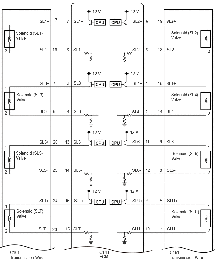
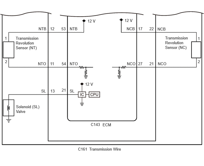
WIRING DIAGRAM
CAUTION / NOTICE / HINT
NOTICE:
Perform registration and/or initialization when parts related to the automatic transaxle are replaced.
Click here
![2025 MY Corolla Corolla Hatchback GR Corolla [09/2024 - ]; UC80F (AUTOMATIC TRANSMISSION / TRANSAXLE): AUTOMATIC TRANSAXLE SYSTEM: PRECAUTION](/t3Portal/stylegraphics/info.gif)
PROCEDURE
|
1. |
READ VALUE USING GTS |
(a) Read the Data List according to the display on the GTS.
Powertrain > Transmission > Data List
|
Tester Display |
Measurement Item |
Range |
Normal Condition |
Diagnostic Note |
|---|---|---|---|---|
|
NT Sensor Speed |
Input shaft speed |
Min.: 0 rpm Max.: 65535 rpm |
|
Data is displayed in increments of 50 rpm |
|
NT Sensor Voltage |
NT sensor voltage |
Min.: 0.000 V Max.: 4.999 V |
0.1 to 1.9 V: Engine idling |
- |
Powertrain > Transmission > Data List
|
Tester Display |
|---|
|
NT Sensor Speed |
|
NT Sensor Voltage |
|
Result |
Proceed to |
|---|---|
|
Data List values are normal |
A |
|
Data List values are not normal |
B |
| B |

|
|

|
2. |
READ VALUE USING GTS (NC SENSOR SPEED AND NC SENSOR VOLTAGE) |
(a) Read the Data List according to the display on the GTS.
Powertrain > Transmission > Data List
|
Tester Display |
Measurement Item |
Range |
Normal Condition |
Diagnostic Note |
|---|---|---|---|---|
|
NC Sensor Speed |
Counter gear speed |
Min.: 0 rpm Max.: 12750 rpm |
- |
- |
|
NC Sensor Voltage |
NC sensor voltage |
Min.: 0.000 V Max.: 4.999 V |
0.1 to 1.9 V: Engine idling |
- |
Powertrain > Transmission > Data List
|
Tester Display |
|---|
|
NC Sensor Speed |
|
NC Sensor Voltage |
|
Result |
Proceed to |
|---|---|
|
Data List values are normal |
A |
|
Data List values are not normal |
B |
| B |
|
|
|
3. |
CHECK HARNESS AND CONNECTOR (TRANSMISSION WIRE (SOLENOID VALVE) - ECM) |
(a) Disconnect the C143 ECM connector.
(b) Measure the resistance according to the value(s) in the table below.
Standard Resistance:
|
Tester Connection |
Condition |
Specified Condition |
|---|---|---|
|
C143-7 (SL1+) - C143-8 (SL1-) |
20°C (68°F) |
5.0 to 5.6 Ω |
|
C143-5 (SL2+) - C143-6 (SL2-) |
20°C (68°F) |
5.0 to 5.6 Ω |
|
C143-3 (SL3+) - C143-4 (SL3-) |
20°C (68°F) |
5.0 to 5.6 Ω |
|
C143-1 (SL4+) - C143-2 (SL4-) |
20°C (68°F) |
5.0 to 5.6 Ω |
|
C143-13 (SL5+) - C143-14 (SL5-) |
20°C (68°F) |
5.0 to 5.6 Ω |
|
C143-11 (SL6+) - C143-12 (SL6-) |
20°C (68°F) |
5.0 to 5.6 Ω |
|
C143-16 (SLT+) - C143-15 (SLT-) |
20°C (68°F) |
5.0 to 5.6 Ω |
|
C143-9 (SLU+) - C143-10 (SLU-) |
20°C (68°F) |
5.0 to 5.6 Ω |
|
C143-21 (SL) - Body ground |
20°C (68°F) |
11 to 15 Ω |
|
C143-7 (SL1+) or C143-8 (SL1-) - Body ground and other terminals |
Always |
10 kΩ or higher |
|
C143-5 (SL2+) or C143-6 (SL2-) - Body ground and other terminals |
Always |
10 kΩ or higher |
|
C143-3 (SL3+) or C143-4 (SL3-) - Body ground and other terminals |
Always |
10 kΩ or higher |
|
C143-1 (SL4+) or C143-2 (SL4-) - Body ground and other terminals |
Always |
10 kΩ or higher |
|
C143-13 (SL5+) or C143-14 (SL5-) - Body ground and other terminals |
Always |
10 kΩ or higher |
|
C143-11 (SL6+) or C143-12 (SL6-) - Body ground and other terminals |
Always |
10 kΩ or higher |
|
C143-16 (SLT+) or C143-15 (SLT-) - Body ground and other terminals |
Always |
10 kΩ or higher |
|
C143-9 (SLU+) or C143-10 (SLU-) - Body ground and other terminals |
Always |
10 kΩ or higher |
| NG |
|
|
|
4. |
CHECK ECM POWER SOURCE CIRCUIT |
Click here
HINT:
Check the ECM power source circuit, and proceed to the next step if no malfunction is recognized.
|
|
5. |
REPLACE ECM |
Click here
| NEXT |
|
|
6. |
CHECK HARNESS AND CONNECTOR (TRANSMISSION WIRE - ECM) |
(a) Disconnect the C161 transmission wire connector.
(b) Disconnect the C143 ECM connector.
(c) Measure the resistance according to the value (s) in the table below.
Standard Resistance:
|
Tester Connection |
Condition |
Specified Condition |
|---|---|---|
|
C161-17 (SL1+) - C143-7 (SL1+) |
Always |
Below 1 Ω |
|
C161-16 (SL1-) - C143-8 (SL1-) |
Always |
Below 1 Ω |
|
C161-19 (SL2+) - C143-5 (SL2+) |
Always |
Below 1 Ω |
|
C161-18 (SL2-) - C143-6 (SL2-) |
Always |
Below 1 Ω |
|
C161-7 (SL3+) - C143-3 (SL3+) |
Always |
Below 1 Ω |
|
C161-6 (SL3-) - C143-4 (SL3-) |
Always |
Below 1 Ω |
|
C161-15 (SL4+) - C143-1 (SL4+) |
Always |
Below 1 Ω |
|
C161-14 (SL4-) - C143-2 (SL4-) |
Always |
Below 1 Ω |
|
C161-26 (SL5+) - C143-13 (SL5+) |
Always |
Below 1 Ω |
|
C161-25 (SL5-) - C143-14 (SL5-) |
Always |
Below 1 Ω |
|
C161-9 (SL6+) - C143-11 (SL6+) |
Always |
Below 1 Ω |
|
C161-8 (SL6-) - C143-12 (SL6-) |
Always |
Below 1 Ω |
|
C161-24 (SLT+) - C143-16 (SLT+) |
Always |
Below 1 Ω |
|
C161-23 (SLT-) - C143-15 (SLT-) |
Always |
Below 1 Ω |
|
C161-5 (SLU+) - C143-9 (SLU+) |
Always |
Below 1 Ω |
|
C161-4 (SLU-) - C143-10 (SLU-) |
Always |
Below 1 Ω |
|
C161-13 (SL) - C143-21 (SL) |
Always |
Below 1 Ω |
|
C161-17 (SL1+) or C143-7 (SL1+) - Body ground and other terminals |
Always |
10 kΩ or higher |
|
C161-16 (SL1-) or C143-8 (SL1-) - Body ground and other terminals |
Always |
10 kΩ or higher |
|
C161-19 (SL2+) or C143-5 (SL2+) - Body ground and other terminals |
Always |
10 kΩ or higher |
|
C161-18 (SL2-) or C143-6 (SL2-) - Body ground and other terminals |
Always |
10 kΩ or higher |
|
C161-7 (SL3+) or C143-3 (SL3+) - Body ground and other terminals |
Always |
10 kΩ or higher |
|
C161-6 (SL3-) or C143-4 (SL3-) - Body ground and other terminals |
Always |
10 kΩ or higher |
|
C161-15 (SL4+) or C143-1 (SL4+) - Body ground and other terminals |
Always |
10 kΩ or higher |
|
C161-14 (SL4-) or C143-2 (SL4-) - Body ground and other terminals |
Always |
10 kΩ or higher |
|
C161-26 (SL5+) or C143-13 (SL5+) - Body ground and other terminals |
Always |
10 kΩ or higher |
|
C161-25 (SL5-) or C143-14 (SL5-) - Body ground and other terminals |
Always |
10 kΩ or higher |
|
C161-9 (SL6+) or C143-11 (SL6+) - Body ground and other terminals |
Always |
10 kΩ or higher |
|
C161-8 (SL6-) or C143-12 (SL6-) - Body ground and other terminals |
Always |
10 kΩ or higher |
|
C161-24 (SLT+) or C143-16 (SLT+) - Body ground and other terminals |
Always |
10 kΩ or higher |
|
C161-23 (SLT-) or C143-15 (SLT-) - Body ground and other terminals |
Always |
10 kΩ or higher |
|
C161-5 (SLU+) or C143-9 (SLU+) - Body ground and other terminals |
Always |
10 kΩ or higher |
|
C161-4 (SLU-) or C143-10 (SLU-) - Body ground and other terminals |
Always |
10 kΩ or higher |
|
C161-13 (SL) or C143-21 (SL) - Body ground and other terminals |
Always |
10 kΩ or higher |
| NG |
|
REPAIR OR REPLACE HARNESS OR CONNECTOR |
|
|
7. |
INSPECT SOLENOID (SL1), (SL2), (SL3), (SL4), (SL5), (SL6), (SLT), (SLU) AND (SL) VALVE |
Click here
| OK |
|
| NG |
|
REPLACE SOLENOID (SL1), (SL2), (SL3), (SL4), (SL5), (SL6), (SLT), (SLU) OR (SL) VALVE |
|
8. |
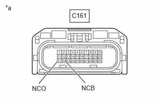
INSPECT TRANSMISSION REVOLUTION SENSOR (NC) (NC TERMINAL) |
|
(a) Disconnect the C161 transmission wire connector. |
|
(b) Measure the resistance according to the value(s) in the table below.
Standard Resistance:
|
Tester Connection |
Condition |
Specified Condition |
|---|---|---|
|
C161-21 (NCO) - Body ground |
Always |
99 to 101 Ω |
(c) Turn the ignition switch to ON.
(d) Measure the voltage according to the value(s) in the table below.
Standard Voltage:
|
Tester Connection |
Switch Condition |
Specified Condition |
|---|---|---|
|
C161-22 (NCB) - Body ground |
Ignition switch ON |
11 to 14 V |
| NG |
|
|
|
9. |
INSPECT TRANSMISSION WIRE (TRANSMISSION REVOLUTION SENSOR (NC)) |
|
(a) Disconnect the transmission revolution sensor (NC) connector.
Click here
|
|
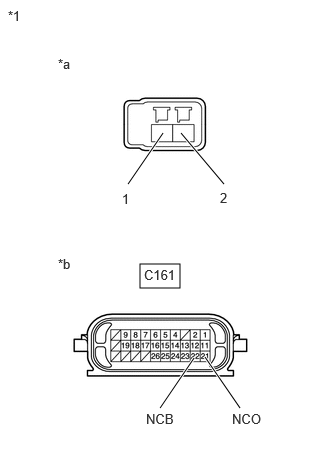
(b) Disconnect the C161 transmission wire connector.
(c) Measure the resistance according to the value(s) in the table below.
Standard Resistance:
|
Tester Connection |
Condition |
Specified Condition |
|---|---|---|
|
1 (transmission revolution sensor (NC) side) - C161-22 (NCB) |
Always |
Below 1 Ω |
|
2 (transmission revolution sensor (NC) side) - C161-21 (NCO) |
Always |
Below 1 Ω |
|
1 (transmission revolution sensor (NC) side) or C161-22 (NCB) - Body ground |
Always |
10 kΩ or higher |
|
2 (transmission revolution sensor (NC) side) or C161-21 (NCO) - Body ground |
Always |
10 kΩ or higher |
| OK |
|
| NG |
|
|
10. |
CHECK HARNESS AND CONNECTOR (TRANSMISSION WIRE - ECM) |
(a) Disconnect the C161 transmission wire connector.
(b) Disconnect the C143 ECM connector.
(c) Measure the resistance according to the value(s) in the table below.
Standard Resistance:
|
Tester Connection |
Condition |
Specified Condition |
|---|---|---|
|
C161-22 (NCB) - C143-17 (NCB) |
Always |
Below 1 Ω |
|
C161-21 (NCO) - C143-27 (NCO) |
Always |
Below 1 Ω |
|
C161-22 (NCB) or C143-17 (NCB) - Body ground |
Always |
10 kΩ or higher |
|
C161-21 (NCO) or C143-27 (NCO) - Body ground |
Always |
10 kΩ or higher |
| NG |
|
REPAIR OR REPLACE HARNESS OR CONNECTOR (TRANSMISSION WIRE - ECM) |
|
|
11. |
REPLACE ECM |
Click here
| NEXT |
|
|
12. |
INSPECT TRANSMISSION REVOLUTION SENSOR (NT) |
|
(a) Disconnect the C161 transmission wire connector. |
|
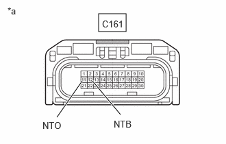
(b) Measure the resistance according to the value(s) in the table below.
Standard Resistance:
|
Tester Connection |
Condition |
Specified Condition |
|---|---|---|
|
C161-11 (NTO) - Body ground |
Always |
99 to 101 Ω |
(c) Turn the ignition switch to ON.
(d) Measure the voltage according to the value(s) in the table below.
Standard Voltage:
|
Tester Connection |
Condition |
Specified Condition |
|---|---|---|
|
C161-12 (NTB) - Body ground |
Ignition switch ON |
11 to 14 V |
| NG |
|
|
|
13. |
INSPECT TRANSMISSION WIRE (TRANSMISSION REVOLUTION SENSOR (NT)) |
|
(a) Disconnect the transmission revolution sensor (NT) connector.
Click here
|
|
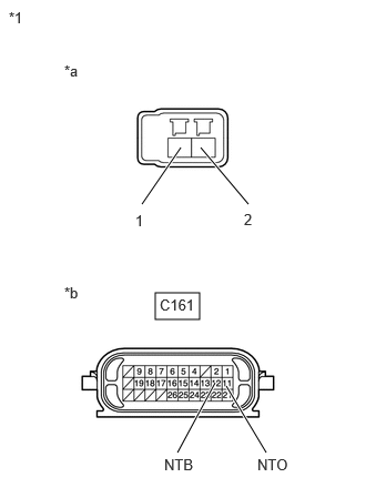
(b) Disconnect the C161 transmission wire connector.
(c) Measure the resistance according to the value(s) in the table below.
Standard Resistance:
|
Tester Connection |
Condition |
Specified Condition |
|---|---|---|
|
1 (transmission revolution sensor (NT) side) - C161-12 (NTB) |
Always |
Below 1 Ω |
|
2 (transmission revolution sensor (NT) side) - C161-11 (NTO) |
Always |
Below 1 Ω |
|
1 (transmission revolution sensor (NT) side) or C161-12 (NTB) - Body ground and other terminals |
Always |
10 kΩ or higher |
|
2 (transmission revolution sensor (NT) side) or C161-11 (NTO) - Body ground and other terminals |
Always |
10 kΩ or higher |
| OK |
|
| NG |
|
|
14. |
CHECK HARNESS AND CONNECTOR (TRANSMISSION WIRE - ECM) |
(a) Disconnect the C161 transmission wire connector.
(b) Disconnect the C143 ECM connector.
(c) Measure the resistance according to the value(s) in the table below.
Standard Resistance:
|
Tester Connection |
Condition |
Specified Condition |
|---|---|---|
|
C161-12 (NTB) - C143-53 (NTB) |
Always |
Below 1 Ω |
|
C161-11 (NTO) - C143-54 (NTO) |
Always |
Below 1 Ω |
|
C161-12 (NTB) or C143-53 (NTB) - Body ground and other terminals |
Always |
10 kΩ or higher |
|
C161-11 (NTO) or C143-54 (NTO) - Body ground and other terminals |
Always |
10 kΩ or higher |
| NG |
|
REPAIR OR REPLACE HARNESS OR CONNECTOR (TRANSMISSION WIRE - ECM) |
|
|
15. |
REPLACE ECM |
Click here
| NEXT |
|
|
|
|