| Last Modified: 01-27-2025 | 6.11:8.1.0 | Doc ID: RM100000002OO4M |
| Model Year Start: 2025 | Model: GR Corolla | Prod Date Range: [09/2024 - ] |
| Title: GF1A (TRANSFER / 4WD / AWD): ACTIVE TORQUE SPLIT AWD SYSTEM: AWD Control Switch Circuit; 2025 MY Corolla Corolla Hatchback GR Corolla [09/2024 - ] | ||
|
AWD Control Switch Circuit |
DESCRIPTION
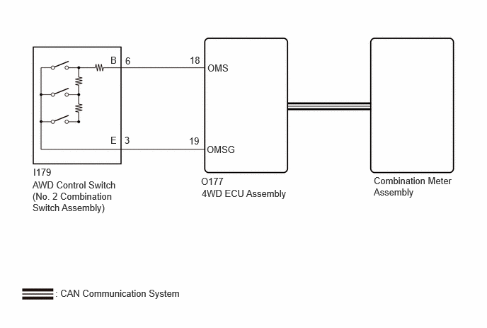
The AWD control switch (No. 2 combination switch assembly) change signal is sent to the 4WD ECU assembly, and then a mode change request signal is sent from the 4WD ECU assembly to the combination meter assembly via CAN communication.
WIRING DIAGRAM
CAUTION / NOTICE / HINT
NOTICE:
When the 4WD ECU assembly is replaced, before removing the 4WD ECU assembly, it is necessary to perform ECU Data Save to save the original 4WD ECU assembly information.
Click here
![2023 - 2025 MY Corolla Corolla Hatchback GR Corolla [09/2022 - ]; GF1A (TRANSFER / 4WD / AWD): ACTIVE TORQUE SPLIT AWD SYSTEM: CALIBRATION](/t3Portal/stylegraphics/info.gif)
PROCEDURE
|
1. |
CHECK CAN COMMUNICATION SYSTEM |
(a) Using the GTS, check for DTCs.
Click here
(b) Check that DTCs indicating a CAN communication system malfunction are not output.
|
Result |
Proceed to |
|---|---|
|
DTCs are not output |
A |
|
DTCs are output |
B |
| B |

|
|

|
2. |
READ VALUE USING GTS (4WD MODE SWITCH) |
(a) Read the Data List according to the display on the GTS.
Chassis > Four Wheel Drive > Data List
|
Tester Display |
Measurement Item |
Range |
Normal Condition |
Diagnostic Note |
|---|---|---|---|---|
|
4WD Mode Switch Front |
AWD control switch (No. 2 combination switch assembly) is in NORMAL mode |
OFF / ON |
OFF: Mode other than NORMAL ON: NORMAL mode |
- |
|
4WD Mode Switch Rear |
AWD control switch (No. 2 combination switch assembly) is in GRAVEL mode |
OFF / ON |
OFF: Mode other than GRAVEL ON: GRAVEL mode |
- |
|
4WD Mode Switch Track |
AWD control switch (No. 2 combination switch assembly) is in TRACK mode |
OFF / ON |
OFF: Mode other than TRACK ON: TRACK mode |
- |
Chassis > Four Wheel Drive > Data List
|
Tester Display |
|---|
|
4WD Mode Switch Front |
|
4WD Mode Switch Rear |
|
4WD Mode Switch Track |
OK:
The display changes in accordance with the operation of the AWD control switch.
| OK |
|
GO TO METER / GAUGE SYSTEM (HOW TO PROCEED WITH TROUBLESHOOTING) |
|
|
3. |
INSPECT AWD CONTROL SWITCH (NO. 2 COMBINATION SWITCH ASSEMBLY) |
Click here
| NG |
|
REPLACE AWD CONTROL SWITCH (NO. 2 COMBINATION SWITCH ASSEMBLY) |
|
|
4. |
CHECK HARNESS AND CONNECTOR (4WD ECU ASSEMBLY - AWD CONTROL SWITCH (NO. 2 COMBINATION SWITCH ASSEMBLY)) |
(a) Turn the ignition switch off.
(b) Disconnect the O177 4WD ECU assembly connector.
(c) Disconnect the I179 AWD control switch (No. 2 combination switch assembly) connector.
(d) Measure the resistance according to the value(s) in the table below.
Standard Resistance:
|
Tester Connection |
Condition |
Specified Condition |
|---|---|---|
|
O177-18 (OMS) - I179-6 (B) |
Always |
Below 1 Ω |
|
O177-19 (OMSG) - I179-3 (E) |
Always |
Below 1 Ω |
|
O177-18 (OMS) or I179-6 (B) - Body ground |
Always |
10 kΩ or higher |
|
O177-19 (OMSG) or I179-3 (E) - Body ground |
Always |
10 kΩ or higher |
|
O177-18 (OMS) or I179-6 (B) - O177-19 (OMSG) or I179-3 (E) |
Always |
10 kΩ or higher |
| OK |
|
| NG |
|
REPAIR OR REPLACE HARNESS OR CONNECTOR |
|
|
|