| Last Modified: 06-05-2026 | 6.11:8.1.0 | Doc ID: RM100000002DUHJ |
| Model Year Start: 2024 | Model: GR Corolla | Prod Date Range: [08/2023 - 09/2024] |
| Title: NETWORKING: CAN COMMUNICATION SYSTEM (for Gasoline Model): TERMINALS OF ECU; 2024 - 2025 MY GR Corolla Corolla Corolla Hatchback [08/2023 - 09/2024] | ||
TERMINALS OF ECU
NOTICE:
-
After the ignition switch is turned off, there may be a waiting time before disconnecting the negative (-) battery terminal.
Click here
![2023 - 2026 MY GR Corolla Corolla Corolla Hatchback Corolla HV [09/2022 - ]; SETUP: WHEN DISCONNECTING OR RECONNECTING BATTERY TERMINAL: BEFORE DISCONNECTING BATTERY](/t3Portal/stylegraphics/info.gif)
-
When disconnecting and reconnecting the battery.
HINT:
When disconnecting and reconnecting the battery, there is an automatic learning function that completes learning when the respective system is used.
Click here
- Before measuring the resistance of the CAN bus, turn the ignition switch off and leave the vehicle for 1 minute or more without operating the key or any switches, or opening or closing the doors. After that, disconnect the cable from the negative (-) battery terminal and leave the vehicle for 10 minutes or more before measuring the resistance.
- This section describes the standard values for all CAN related components.
HINT:
-
The systems (ECUs and sensors) that use CAN communication vary depending on the vehicle and optional equipment. Check which systems (ECUs and sensors) are installed to the vehicle.
Click here
- Operating the ignition switch, any other switches or a door triggers related ECU and sensor communication on the CAN. This communication will cause the resistance value to change.
- Even after DTCs are cleared, if a DTC is stored again after driving the vehicle for a while, the malfunction may be occurring due to vibration of the vehicle. In such a case, wiggling the ECUs or wire harness while performing the inspection below may help determine the cause of the malfunction.
1. NO. 10 CAN JUNCTION CONNECTOR (except G16E-GTS)
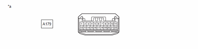
(a) Check the No. 10 CAN junction connector.
(1) Connection diagram
|
*a |
Front view of wire harness connector (to No. 10 CAN Junction Connector) |
- |
- |
(2) Check the connection diagram of the components which are connected to the No. 10 CAN junction connector.
|
Terminal No. (Symbol) |
Wiring Color |
Connected to |
|---|---|---|
|
A179-2 (CANH) |
R |
Brake actuator assembly (for Bus 4) |
|
A179-13 (CANL) |
W |
|
|
A179-3 (CANH) |
B |
No. 13 CAN junction connector (for Bus 4) |
|
A179-14 (CANL) |
W |
|
|
A179-4 (CANH) |
G |
Central gateway ECU (network gateway ECU) (for Bus 4) |
|
A179-15 (CANL) |
W |
2. NO. 10 CAN JUNCTION CONNECTOR (for G16E-GTS)
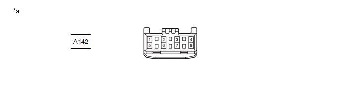
(a) Check the No. 10 CAN junction connector.
(1) Connection diagram
|
*a |
Front view of wire harness connector (to No. 10 CAN Junction Connector) |
- |
- |
(2) Check the connection diagram of the components which are connected to the No. 10 CAN junction connector.
|
Terminal No. (Symbol) |
Wiring Color |
Connected to |
|---|---|---|
|
A142-2 (CANH) |
R |
Brake actuator assembly (for Bus 4) |
|
A142-6 (CANL) |
W |
|
|
A142-3 (CANH) |
B |
No. 13 CAN junction connector (for Bus 4) |
|
A142-7 (CANL) |
W |
|
|
A142-4 (CANH) |
G |
Central gateway ECU (network gateway ECU) (for Bus 4) |
|
A142-8 (CANL) |
W |
3. NO. 11 CAN JUNCTION CONNECTOR (except G16E-GTS)
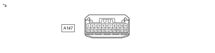
(a) Check the No. 11 CAN junction connector.
(1) Connection diagram
|
*a |
Front view of wire harness connector (to No. 11 CAN Junction Connector) |
- |
- |
(2) Check the connection diagram of the components which are connected to the No. 11 CAN junction connector.
|
Terminal No. (Symbol) |
Wiring Color |
Connected to |
|---|---|---|
|
A147-1 (CANH) |
B |
ECM (for Chassis Local Bus) |
|
A147-12 (CANL) |
W |
|
|
A147-2 (CANH) |
LG |
Brake actuator assembly (for Chassis Local Bus) |
|
A147-13 (CANL) |
W |
|
|
A147-5 (CANH) |
G |
TCM* (for Bus 2) |
|
A147-16 (CANL) |
W |
|
|
A147-6 (CANH) |
R |
ECM (for Bus 2) |
|
A147-17 (CANL) |
W |
|
|
A147-7 (CANH) |
P |
Central gateway ECU (network gateway ECU) (for Bus 2) |
|
A147-18 (CANL) |
W |
- *: for CVT (K120)
4. NO. 12 CAN JUNCTION CONNECTOR (except G16E-GTS)
(a) Check the No. 12 CAN junction connector.
(1) Connection diagram

|
*a |
Front view of wire harness connector (to No. 12 CAN Junction Connector) |
- |
- |
(2) Check the connection diagram of the components which are connected to the No. 12 CAN junction connector.
|
Terminal No. (Symbol) |
Wiring Color |
Connected to |
|---|---|---|
|
A180-1 (CANH) |
L |
Main body ECU (multiplex network body ECU) (for Bus 5) |
|
A180-12 (CANL) |
W |
|
|
A180-2 (CANH) |
G |
No. 17 CAN junction connector (for Bus 5) |
|
A180-13 (CANL) |
W |
5. NO. 13 CAN JUNCTION CONNECTOR
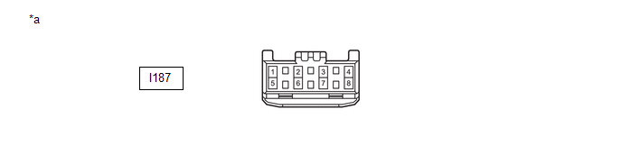
(a) Check the No. 13 CAN junction connector.
(1) Connection diagram
|
*a |
Front view of wire harness connector (to No. 13 CAN Junction Connector) |
- |
- |
(2) Check the connection diagram of the components which are connected to the No. 13 CAN junction connector.
|
Terminal No. (Symbol) |
Wiring Color |
Connected to |
|---|---|---|
|
I187-1 (CANH) |
R |
Airbag sensor assembly (for Bus 4) |
|
I187-5 (CANL) |
W |
|
|
I187-2 (CANH) |
B |
No. 10 CAN junction connector (for Bus 4) |
|
I187-6 (CANL) |
W |
|
|
I187-3 (CANH) |
P |
Steering sensor (for Bus 4) |
|
I187-7 (CANL) |
W |
|
|
I187-4 (CANH) |
G |
Power steering ECU with motor assembly (for Bus 4) |
|
I187-8 (CANL) |
W |
6. NO. 15 CAN JUNCTION CONNECTOR (except G16E-GTS)
(a) Check the No. 15 CAN junction connector.
(1) Connection diagram
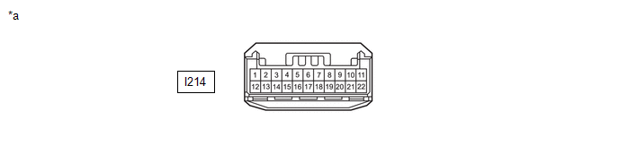
|
*a |
Front view of wire harness connector (to No. 15 CAN Junction Connector) |
- |
- |
(2) Check the connection diagram of the components which are connected to the No. 15 CAN junction connector.
|
Terminal No. (Symbol) |
Wiring Color |
Connected to |
|---|---|---|
|
I214-1 (CANH) |
L |
Radio and display receiver assembly (for Bus 3) |
|
I214-12 (CANL) |
W |
|
|
I214-2 (CANH) |
GR |
DCM (telematics transceiver)* (for Bus 3) |
|
I214-13 (CANL) |
W |
|
|
I214-3 (CANH) |
G |
Central gateway ECU (network gateway ECU) (for Bus 3) |
|
I214-14 (CANL) |
W |
|
|
I214-4 (CANH) |
B |
Combination meter assembly (for Bus 3) |
|
I214-15 (CANL) |
W |
- *: w/ Telematics Transceiver
7. NO. 15 CAN JUNCTION CONNECTOR (for G16E-GTS)
(a) Check the No. 15 CAN junction connector.
(1) Connection diagram
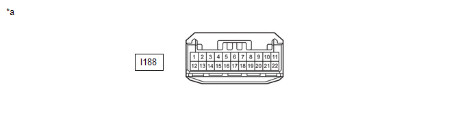
|
*a |
Front view of wire harness connector (to No. 15 CAN Junction Connector) |
- |
- |
(2) Check the connection diagram of the components which are connected to the No. 15 CAN junction connector.
|
Terminal No. (Symbol) |
Wiring Color |
Connected to |
|---|---|---|
|
I188-1 (CANH) |
B |
Combination meter assembly (for Bus 3) |
|
I188-12 (CANL) |
W |
|
|
I188-2 (CANH) |
G |
Central gateway ECU (network gateway ECU) (for Bus 3) |
|
I188-13 (CANL) |
W |
|
|
I188-3 (CANH) |
GR |
DCM (telematics transceiver) (for Bus 3) |
|
I188-14 (CANL) |
W |
|
|
I188-4 (CANH) |
B |
Radio and display receiver assembly* (for Bus 3) |
|
I188-15 (CANL) |
W |
- *: w/ Radio and Display Receiver Assembly
8. NO. 16 CAN JUNCTION CONNECTOR (for Hatchback except G16E-GTS)
(a) Check the No. 16 CAN junction connector.
(1) Connection diagram
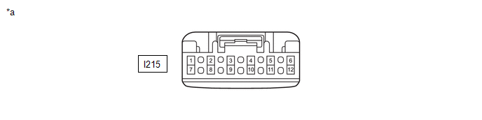
|
*a |
Front view of wire harness connector (to No. 16 CAN Junction Connector) |
- |
- |
(2) Check the connection diagram of the components which are connected to the No. 16 CAN junction connector.
|
Terminal No. (Symbol) |
Wiring Color |
Connected to |
|---|---|---|
|
I215-1 (CANH) |
V |
Central gateway ECU (network gateway ECU) (for Bus 6) |
|
I215-7 (CANL) |
W |
|
|
I215-2 (CANH) |
B |
Central gateway ECU (network gateway ECU) (for Bus 6) |
|
I215-8 (CANL) |
W |
|
|
I215-3 (CANH) |
P |
Tire pressure warning ECU and receiver* (for Bus 6) |
|
I215-9 (CANL) |
W |
- *: w/ Tire Pressure Warning System
9. NO. 16 CAN JUNCTION CONNECTOR (for Sedan except G16E-GTS)
(a) Check the No. 16 CAN junction connector.
(1) Connection diagram
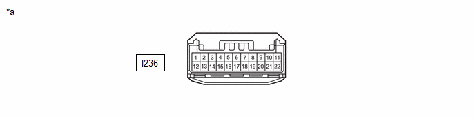
|
*a |
Front view of wire harness connector (to No. 16 CAN Junction Connector) |
- |
- |
(2) Check the connection diagram of the components which are connected to the No. 16 CAN junction connector.
|
Terminal No. (Symbol) |
Wiring Color |
Connected to |
|---|---|---|
|
I236-1 (CANH) |
V |
Central gateway ECU (network gateway ECU) (for Bus 6) |
|
I236-12 (CANL) |
W |
|
|
I236-2 (CANH) |
B |
Central gateway ECU (network gateway ECU) (for Bus 6) |
|
I236-13 (CANL) |
W |
|
|
I236-3 (CANH) |
P |
Tire pressure warning ECU and receiver* (for Bus 6) |
|
I236-14 (CANL) |
W |
- *: w/ Tire Pressure Warning System
10. NO. 16 CAN JUNCTION CONNECTOR (for G16E-GTS)
(a) Check the No. 16 CAN junction connector.
(1) Connection diagram
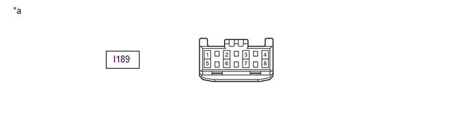
|
*a |
Front view of wire harness connector (to No. 16 CAN Junction Connector) |
- |
- |
(2) Check the connection diagram of the components which are connected to the No. 16 CAN junction connector.
|
Terminal No. (Symbol) |
Wiring Color |
Connected to |
|---|---|---|
|
I189-1 (CANH) |
G |
4WD ECU assembly (for Bus 6) |
|
I189-5 (CANL) |
W |
|
|
I189-2 (CANH) |
V |
Central gateway ECU (network gateway ECU) (for Bus 6) |
|
I189-6 (CANL) |
W |
|
|
I189-3 (CANH) |
B |
Central gateway ECU (network gateway ECU) (for Bus 6) |
|
I189-7 (CANL) |
W |
|
|
I189-4 (CANH) |
P |
Tire pressure warning ECU and receiver (for Bus 6) |
|
I189-8 (CANL) |
W |
11. NO. 17 CAN JUNCTION CONNECTOR (except G16E-GTS)
(a) Check the No. 17 CAN junction connector.
(1) Connection diagram
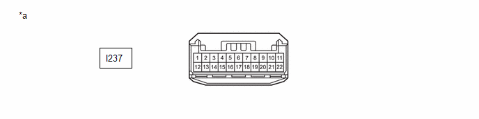
|
*a |
Front view of wire harness connector (to No. 17 CAN Junction Connector) |
- |
- |
(2) Check the connection diagram of the components which are connected to the No. 17 CAN junction connector.
|
Terminal No. (Symbol) |
Wiring Color |
Connected to |
|---|---|---|
|
I237-1 (CANH) |
R |
Certification ECU (smart key ECU assembly)* (for Bus 5) |
|
I237-12 (CANL) |
W |
|
|
I237-2 (CANH) |
LG |
Air conditioning amplifier assembly (for Bus 5) |
|
I237-13 (CANL) |
W |
|
|
I237-3 (CANH) |
B |
Central gateway ECU (network gateway ECU) (for Bus 5) |
|
I237-14 (CANL) |
W |
|
|
I237-4 (CANH) |
SB |
No. 12 CAN junction connector (for Bus 5) |
|
I237-15 (CANL) |
W |
- *: w/ Smart Key System
12. NO. 17 CAN JUNCTION CONNECTOR (for G16E-GTS)
(a) Check the No. 17 CAN junction connector.
(1) Connection diagram
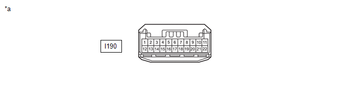
|
*a |
Front view of wire harness connector (to No. 17 CAN Junction Connector) |
- |
- |
(2) Check the connection diagram of the components which are connected to the No. 17 CAN junction connector.
|
Terminal No. (Symbol) |
Wiring Color |
Connected to |
|---|---|---|
|
I190-8 (CANH) |
B |
Main body ECU (multiplex network body ECU) (for Bus 5) |
|
I190-19 (CANL) |
W |
|
|
I190-9 (CANH) |
R |
Certification ECU (smart key ECU assembly) (for Bus 5) |
|
I190-20 (CANL) |
W |
|
|
I190-10 (CANH) |
LG |
Air conditioning amplifier assembly (for Bus 5) |
|
I190-21 (CANL) |
W |
|
|
I190-11 (CANH) |
B |
Central gateway ECU (network gateway ECU) (for Bus 5) |
|
I190-22 (CANL) |
W |
13. NO. 18 CAN JUNCTION CONNECTOR
(a) Check the No. 18 CAN junction connector.
(1) Connection diagram
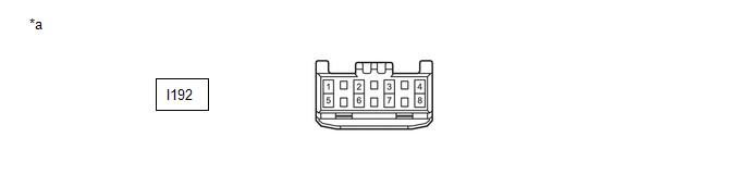
|
*a |
Front view of wire harness connector (to No. 18 CAN Junction Connector) |
- |
- |
(2) Check the connection diagram of the components which are connected to the No. 18 CAN junction connector.
|
Terminal No. (Symbol) |
Wiring Color |
Connected to |
|---|---|---|
|
I192-1 (CANH) |
GR |
Forward recognition camera*1 (for Bus 1) |
|
I192-5 (CANL) |
W |
|
|
I192-2 (CANH) |
GR |
Forward recognition camera*2*3 (for Bus 1) |
|
I192-6 (CANL) |
W |
|
|
I192-2 (CANH) |
GR |
No. 19 CAN junction connector*4 (for Bus 1) |
|
I192-6 (CANL) |
W |
|
|
I192-3 (CANH) |
SB |
Central gateway ECU (network gateway ECU)*2 (for Bus 1) |
|
I192-7 (CANL) |
W |
|
|
I192-3 (CANH) |
G |
Clearance warning ECU assembly*5 (for Bus 1) |
|
I192-7 (CANL) |
W |
|
|
I192-4 (CANH) |
SB |
Central gateway ECU (network gateway ECU)*1 (for Bus 1) |
|
I192-8 (CANL) |
W |
- *1: for G16E-GTS
- *2: except G16E-GTS
- *3: w/ Front Camera System
- *4: w/o Front Camera System
- *5: w/ Intuitive Parking Assist System
14. NO. 19 CAN JUNCTION CONNECTOR (for Hatchback except G16E-GTS)
(a) Check the No. 19 CAN junction connector.
(1) Connection diagram
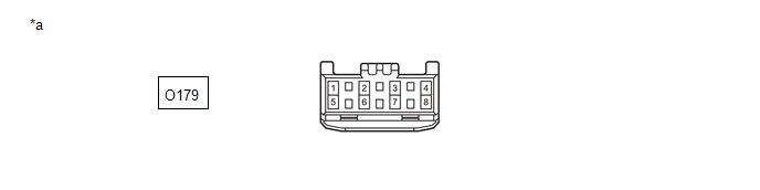
|
*a |
Front view of wire harness connector (to No. 19 CAN Junction Connector) |
- |
- |
(2) Check the connection diagram of the components which are connected to the No. 19 CAN junction connector.
|
Terminal No. (Symbol) |
Wiring Color |
Connected to |
|---|---|---|
|
O179-1 (CANH) |
BE |
Millimeter wave radar sensor assembly (for Bus 1) |
|
O179-5 (CANL) |
W |
|
|
O179-2 (CANH) |
R |
CAN junction terminal (for Bus 1) |
|
O179-6 (CANL) |
W |
|
|
O179-3 (CANH) |
G |
Blind spot monitor sensor LH (B)* (for Bus 1) |
|
O179-7 (CANL) |
W |
- *: w/ Blind Spot Monitor System
15. NO. 19 CAN JUNCTION CONNECTOR (for Sedan)
(a) Check the No. 19 CAN junction connector.
(1) Connection diagram
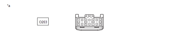
|
*a |
Front view of wire harness connector (to No. 19 CAN Junction Connector) |
- |
- |
(2) Check the connection diagram of the components which are connected to the No. 19 CAN junction connector.
|
Terminal No. (Symbol) |
Wiring Color |
Connected to |
|---|---|---|
|
O203-1 (CANH) |
BE |
Millimeter wave radar sensor assembly*1 (for Bus 1) |
|
O203-5 (CANL) |
W |
|
|
O203-1 (CANH) |
BE |
No. 18 CAN junction connector*2 (for Bus 1) |
|
O203-5 (CANL) |
W |
|
|
O203-2 (CANH) |
R |
CAN junction terminal (for Bus 1) |
|
O203-6 (CANL) |
W |
|
|
O203-3 (CANH) |
G |
Blind spot monitor sensor LH (B)*3 (for Bus 1) |
|
O203-7 (CANL) |
W |
- *1: w/ Front Camera System
- *2: w/o Front Camera System
- *3: w/ Blind Spot Monitor System
16. NO. 19 CAN JUNCTION CONNECTOR (for G16E-GTS)
(a) Check the No. 19 CAN junction connector.
(1) Connection diagram
|
*a |
Front view of wire harness connector (to No. 19 CAN Junction Connector) |
- |
- |
(2) Check the connection diagram of the components which are connected to the No. 19 CAN junction connector.
|
Terminal No. (Symbol) |
Wiring Color |
Connected to |
|---|---|---|
|
O179-1 (CANH) |
R |
CAN junction terminal (for Bus 1) |
|
O179-5 (CANL) |
W |
|
|
O179-3 (CANH) |
G |
Blind spot monitor sensor LH (B)* (for Bus 1) |
|
O179-7 (CANL) |
W |
|
|
O179-4 (CANH) |
BE |
Millimeter wave radar sensor assembly (for Bus 1) |
|
O179-8 (CANL) |
W |
- *: w/ Blind Spot Monitor System
17. CAN JUNCTION TERMINAL
(a) Check the CAN junction terminal.
(1) Connection diagram
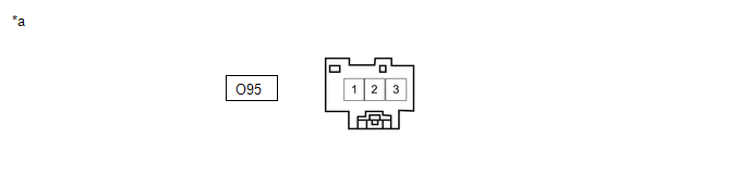
|
*a |
Front view of wire harness connector (to CAN Junction Terminal) |
- |
- |
(2) Check the connection diagram of the components which are connected to the CAN junction terminal.
|
Terminal No. (Symbol) |
Wiring Color |
Connected to |
|---|---|---|
|
O95-3 (CANH) |
R |
No. 19 CAN junction connector (for Bus 1) |
|
O95-2 (CANL) |
W |
18. DLC3
(a) Disconnect the cable from the negative (-) battery terminal.
(b) Measure the resistance according to the value(s) in the table below.
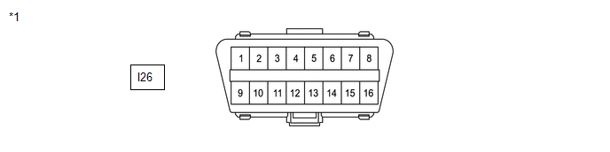
|
*1 |
DLC3 |
- |
- |
Standard Resistance
|
Terminal No. (Symbol) |
Terminal Description |
Condition |
Specified Condition |
|---|---|---|---|
|
I26-6 (CANH) - I26-14 (CANL) |
HIGH-level CAN bus line - LOW-level CAN bus line |
Cable disconnected from negative (-) battery terminal |
54 to 69 Ω |
|
I26-6 (CANH) - I26-4 (CG) |
HIGH-level CAN bus line - Ground |
Cable disconnected from negative (-) battery terminal |
200 Ω or higher |
|
I26-14 (CANL) - I26-4 (CG) |
LOW-level CAN bus line - Ground |
Cable disconnected from negative (-) battery terminal |
200 Ω or higher |
|
I26-6 (CANH) - I26-16 (BAT) |
HIGH-level CAN bus line - Battery positive (+) |
Cable disconnected from negative (-) battery terminal |
6 kΩ or higher |
|
I26-14 (CANL) - I26-16 (BAT) |
LOW-level CAN bus line - Battery positive (+) |
Cable disconnected from negative (-) battery terminal |
6 kΩ or higher |
19. CENTRAL GATEWAY ECU (NETWORK GATEWAY ECU)
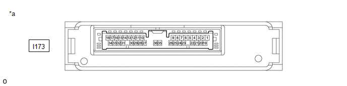
|
*a |
Component without harness connected (Central Gateway ECU (Network Gateway ECU)) |
- |
- |
(a) Disconnect the cable from the negative (-) battery terminal.
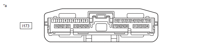
(b) Disconnect the I173 central gateway ECU (network gateway ECU) connector.
(c) Measure the resistance according to the value(s) in the table below.
|
*a |
Front view of wire harness connector (to Central Gateway ECU (Network Gateway ECU)) |
- |
- |
Diagnosis Bus Branch Lines (DLC3 - Central gateway ECU (network gateway ECU))
|
Terminal No. (Symbol) |
Terminal Description |
Condition |
Specified Condition |
|---|---|---|---|
|
I173-16 (CA6H) - I173-17 (CA6L) |
HIGH-level CAN bus line - LOW-level CAN bus line |
Cable disconnected from negative (-) battery terminal |
1 MΩ or higher |
|
I173-16 (CA6H) - I173-22 (GND) |
HIGH-level CAN bus line - Ground |
Cable disconnected from negative (-) battery terminal |
200 Ω or higher |
|
I173-17 (CA6L) - I173-22 (GND) |
LOW-level CAN bus line - Ground |
Cable disconnected from negative (-) battery terminal |
200 Ω or higher |
|
I173-16 (CA6H) - I173-1 (BATT) |
HIGH-level CAN bus line - Battery positive (+) |
Cable disconnected from negative (-) battery terminal |
6 kΩ or higher |
|
I173-17 (CA6L) - I173-1 (BATT) |
LOW-level CAN bus line - Battery positive (+) |
Cable disconnected from negative (-) battery terminal |
6 kΩ or higher |
Bus 1 Main Lines
|
Terminal No. (Symbol) |
Terminal Description |
Condition |
Specified Condition |
|---|---|---|---|
|
I173-28 (CA1H) - I173-27 (CA1L) |
HIGH-level CAN bus line - LOW-level CAN bus line |
Cable disconnected from negative (-) battery terminal |
108 to 132 Ω |
|
I173-28 (CA1H) - I173-22 (GND) |
HIGH-level CAN bus line - Ground |
Cable disconnected from negative (-) battery terminal |
200 Ω or higher |
|
I173-27 (CA1L) - I173-22 (GND) |
LOW-level CAN bus line - Ground |
Cable disconnected from negative (-) battery terminal |
200 Ω or higher |
|
I173-28 (CA1H) - I173-1 (BATT) |
HIGH-level CAN bus line - Battery positive (+) |
Cable disconnected from negative (-) battery terminal |
6 kΩ or higher |
|
I173-27 (CA1L) - I173-1 (BATT) |
LOW-level CAN bus line - Battery positive (+) |
Cable disconnected from negative (-) battery terminal |
6 kΩ or higher |
Bus 2 Main Lines
|
Terminal No. (Symbol) |
Terminal Description |
Condition |
Specified Condition |
|---|---|---|---|
|
I173-26 (CA4H) - I173-25 (CA4L) |
HIGH-level CAN bus line - LOW-level CAN bus line |
Cable disconnected from negative (-) battery terminal |
108 to 132 Ω |
|
I173-26 (CA4H) - I173-22 (GND) |
HIGH-level CAN bus line - Ground |
Cable disconnected from negative (-) battery terminal |
200 Ω or higher |
|
I173-25 (CA4L) - I173-22 (GND) |
LOW-level CAN bus line - Ground |
Cable disconnected from negative (-) battery terminal |
200 Ω or higher |
|
I173-26 (CA4H) - I173-1 (BATT) |
HIGH-level CAN bus line - Battery positive (+) |
Cable disconnected from negative (-) battery terminal |
6 kΩ or higher |
|
I173-25 (CA4L) - I173-1 (BATT) |
LOW-level CAN bus line - Battery positive (+) |
Cable disconnected from negative (-) battery terminal |
6 kΩ or higher |
Bus 3 Main Lines
|
Terminal No. (Symbol) |
Terminal Description |
Condition |
Specified Condition |
|---|---|---|---|
|
I173-30 (CA3H) - I173-29 (CA3L) |
HIGH-level CAN bus line - LOW-level CAN bus line |
Cable disconnected from negative (-) battery terminal |
108 to 132 Ω |
|
I173-30 (CA3H) - I173-22 (GND) |
HIGH-level CAN bus line - Ground |
Cable disconnected from negative (-) battery terminal |
200 Ω or higher |
|
I173-29 (CA3L) - I173-22 (GND) |
LOW-level CAN bus line - Ground |
Cable disconnected from negative (-) battery terminal |
200 Ω or higher |
|
I173-30 (CA3H) - I173-1 (BATT) |
HIGH-level CAN bus line - Battery positive (+) |
Cable disconnected from negative (-) battery terminal |
6 kΩ or higher |
|
I173-29 (CA3L) - I173-1 (BATT) |
LOW-level CAN bus line - Battery positive (+) |
Cable disconnected from negative (-) battery terminal |
6 kΩ or higher |
Bus 4 Main Lines
|
Terminal No. (Symbol) |
Terminal Description |
Condition |
Specified Condition |
|---|---|---|---|
|
I173-24 (CA2H) - I173-23 (CA2L) |
HIGH-level CAN bus line - LOW-level CAN bus line |
Cable disconnected from negative (-) battery terminal |
108 to 132 Ω |
|
I173-24 (CA2H) - I173-22 (GND) |
HIGH-level CAN bus line - Ground |
Cable disconnected from negative (-) battery terminal |
200 Ω or higher |
|
I173-23 (CA2L) - I173-22 (GND) |
LOW-level CAN bus line - Ground |
Cable disconnected from negative (-) battery terminal |
200 Ω or higher |
|
I173-24 (CA2H) - I173-1 (BATT) |
HIGH-level CAN bus line - Battery positive (+) |
Cable disconnected from negative (-) battery terminal |
6 kΩ or higher |
|
I173-23 (CA2L) - I173-1 (BATT) |
LOW-level CAN bus line - Battery positive (+) |
Cable disconnected from negative (-) battery terminal |
6 kΩ or higher |
Bus 5 Main Lines
|
Terminal No. (Symbol) |
Terminal Description |
Condition |
Specified Condition |
|---|---|---|---|
|
I173-7 (CA5H) - I173-8 (CA5L) |
HIGH-level CAN bus line - LOW-level CAN bus line |
Cable disconnected from negative (-) battery terminal |
108 to 132 Ω |
|
I173-7 (CA5H) - I173-22 (GND) |
HIGH-level CAN bus line - Ground |
Cable disconnected from negative (-) battery terminal |
200 Ω or higher |
|
I173-8 (CA5L) - I173-22 (GND) |
LOW-level CAN bus line - Ground |
Cable disconnected from negative (-) battery terminal |
200 Ω or higher |
|
I173-7 (CA5H) - I173-1 (BATT) |
HIGH-level CAN bus line - Battery positive (+) |
Cable disconnected from negative (-) battery terminal |
6 kΩ or higher |
|
I173-8 (CA5L) - I173-1 (BATT) |
LOW-level CAN bus line - Battery positive (+) |
Cable disconnected from negative (-) battery terminal |
6 kΩ or higher |
Bus 6 Main Lines
|
Terminal No. (Symbol) |
Terminal Description |
Condition |
Specified Condition |
|---|---|---|---|
|
I173-31 (CA7H) - I173-10 (CAVH) |
HIGH-level CAN bus line - HIGH-level CAN bus line |
Cable disconnected from negative (-) battery terminal |
Below 1 Ω |
|
I173-32 (CA7L) - I173-11 (CAVL) |
LOW-level CAN bus line - LOW-level CAN bus line |
Cable disconnected from negative (-) battery terminal |
Below 1 Ω |
|
I173-31 (CA7H) - I173-22 (GND) |
HIGH-level CAN bus line - Ground |
Cable disconnected from negative (-) battery terminal |
200 Ω or higher |
|
I173-32 (CA7L) - I173-22 (GND) |
LOW-level CAN bus line - Ground |
Cable disconnected from negative (-) battery terminal |
200 Ω or higher |
|
I173-31 (CA7H) - I173-1 (BATT) |
HIGH-level CAN bus line - Battery positive (+) |
Cable disconnected from negative (-) battery terminal |
6 kΩ or higher |
|
I173-32 (CA7L) - I173-1 (BATT) |
LOW-level CAN bus line - Battery positive (+) |
Cable disconnected from negative (-) battery terminal |
6 kΩ or higher |
Bus 7 Main Lines
|
Terminal No. (Symbol) |
Terminal Description |
Condition |
Specified Condition |
|---|---|---|---|
|
I173-5 (CA8H) - I173-6 (CA8L) |
HIGH-level CAN bus line - LOW-level CAN bus line |
Cable disconnected from negative (-) battery terminal |
108 to 132 Ω |
|
I173-5 (CA8H) - I173-22 (GND) |
HIGH-level CAN bus line - Ground |
Cable disconnected from negative (-) battery terminal |
200 Ω or higher |
|
I173-6 (CA8L) - I173-22 (GND) |
LOW-level CAN bus line - Ground |
Cable disconnected from negative (-) battery terminal |
200 Ω or higher |
|
I173-5 (CA8H) - I173-1 (BATT) |
HIGH-level CAN bus line - Battery positive (+) |
Cable disconnected from negative (-) battery terminal |
6 kΩ or higher |
|
I173-6 (CA8L) - I173-1 (BATT) |
LOW-level CAN bus line - Battery positive (+) |
Cable disconnected from negative (-) battery terminal |
6 kΩ or higher |
20. STEERING SENSOR (except G16E-GTS)
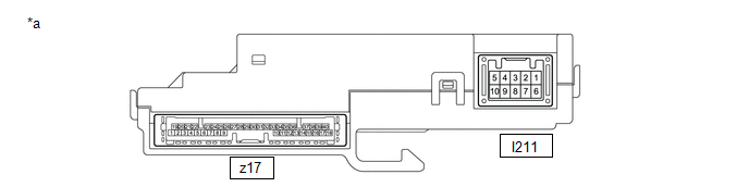
|
*a |
Component without harness connected (Steering Sensor) |
- |
- |
(a) Disconnect the cable from the negative (-) battery terminal.
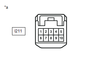
(b) Disconnect the I211 steering sensor connector.
(c) Measure the resistance according to the value(s) in the table below.
|
*a |
Front view of wire harness connector (to Steering Sensor) |
Standard Resistance
|
Terminal No. (Symbol) |
Terminal Description |
Condition |
Specified Condition |
|---|---|---|---|
|
I211-3 (CANH) - I211-8 (CANL) |
HIGH-level CAN bus line - LOW-level CAN bus line |
Cable disconnected from negative (-) battery terminal |
54 to 69 Ω |
|
I211-3 (CANH) - I211-6 (ESS) |
HIGH-level CAN bus line - Ground |
Cable disconnected from negative (-) battery terminal |
200 Ω or higher |
|
I211-8 (CANL) - I211-6 (ESS) |
LOW-level CAN bus line - Ground |
Cable disconnected from negative (-) battery terminal |
200 Ω or higher |
|
I211-3 (CANH) - I211-4 (BAT) |
HIGH-level CAN bus line - Battery positive (+) |
Cable disconnected from negative (-) battery terminal |
6 kΩ or higher |
|
I211-8 (CANL) - I211-4 (BAT) |
LOW-level CAN bus line - Battery positive (+) |
Cable disconnected from negative (-) battery terminal |
6 kΩ or higher |
21. STEERING SENSOR (for G16E-GTS)
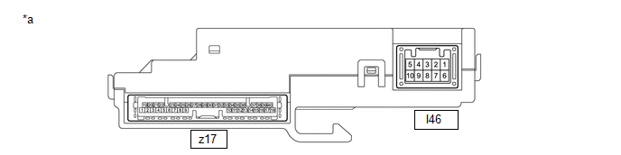
|
*a |
Component without harness connected (Steering Sensor) |
- |
- |
(a) Disconnect the cable from the negative (-) battery terminal.
(b) Disconnect the I46 steering sensor connector.
(c) Measure the resistance according to the value(s) in the table below.
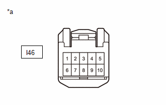
|
*a |
Front view of wire harness connector (to Steering Sensor) |
Standard Resistance
|
Terminal No. (Symbol) |
Terminal Description |
Condition |
Specified Condition |
|---|---|---|---|
|
I46-3 (CANH) - I46-8 (CANL) |
HIGH-level CAN bus line - LOW-level CAN bus line |
Cable disconnected from negative (-) battery terminal |
54 to 69 Ω |
|
I46-3 (CANH) - I46-6 (ESS) |
HIGH-level CAN bus line - Ground |
Cable disconnected from negative (-) battery terminal |
200 Ω or higher |
|
I46-8 (CANL) - I46-6 (ESS) |
LOW-level CAN bus line - Ground |
Cable disconnected from negative (-) battery terminal |
200 Ω or higher |
|
I46-3 (CANH) - I46-4 (BAT) |
HIGH-level CAN bus line - Battery positive (+) |
Cable disconnected from negative (-) battery terminal |
6 kΩ or higher |
|
I46-8 (CANL) - I46-4 (BAT) |
LOW-level CAN bus line - Battery positive (+) |
Cable disconnected from negative (-) battery terminal |
6 kΩ or higher |
22. ECM (for M20A-FKS (CVT (K120)))
Refer to Terminals of ECU.
Click here
(a) Disconnect the cable from the negative (-) battery terminal.
(b) Disconnect the A47 ECM connector.
(c) Measure the resistance according to the value(s) in the table below.
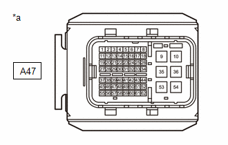
|
*a |
Front view of wire harness connector (to ECM) |
Bus 2 Main Lines
|
Terminal No. (Symbol) |
Terminal Description |
Condition |
Specified Condition |
|---|---|---|---|
|
A47-8 (CANH) - A47-18 (CANL) |
HIGH-level CAN bus line - LOW-level CAN bus line |
Cable disconnected from negative (-) battery terminal |
108 to 132 Ω |
|
A47-8 (CANH) - A47-10 (E1) |
HIGH-level CAN bus line - Ground |
Cable disconnected from negative (-) battery terminal |
200 Ω or higher |
|
A47-18 (CANL) - A47-10 (E1) |
LOW-level CAN bus line - Ground |
Cable disconnected from negative (-) battery terminal |
200 Ω or higher |
|
A47-8 (CANH) - A47-1 (BATT) |
HIGH-level CAN bus line - Battery positive (+) |
Cable disconnected from negative (-) battery terminal |
6 kΩ or higher |
|
A47-18 (CANL) - A47-1 (BATT) |
LOW-level CAN bus line - Battery positive (+) |
Cable disconnected from negative (-) battery terminal |
6 kΩ or higher |
Chassis Local Bus Main Lines
|
Terminal No. (Symbol) |
Terminal Description |
Condition |
Specified Condition |
|---|---|---|---|
|
A47-7 (CAN+) - A47-17 (CAN-) |
HIGH-level CAN bus line - LOW-level CAN bus line |
Cable disconnected from negative (-) battery terminal |
108 to 132 Ω |
|
A47-7 (CAN+) - A47-10 (E1) |
HIGH-level CAN bus line - Ground |
Cable disconnected from negative (-) battery terminal |
200 Ω or higher |
|
A47-17 (CAN-) - A47-10 (E1) |
LOW-level CAN bus line - Ground |
Cable disconnected from negative (-) battery terminal |
200 Ω or higher |
|
A47-7 (CAN+) - A47-1 (BATT) |
HIGH-level CAN bus line - Battery positive (+) |
Cable disconnected from negative (-) battery terminal |
6 kΩ or higher |
|
A47-17 (CAN-) - A47-1 (BATT) |
LOW-level CAN bus line - Battery positive (+) |
Cable disconnected from negative (-) battery terminal |
6 kΩ or higher |
23. ECM (for M20A-FKS (CVT (K121)))
Refer to Terminals of ECU.
Click here
(a) Disconnect the cable from the negative (-) battery terminal.
(b) Disconnect the A178 ECM connector.
(c) Measure the resistance according to the value(s) in the table below.
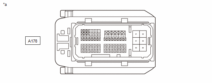
|
*a |
Front view of wire harness connector (to ECM) |
- |
- |
Bus 2 Main Lines
|
Terminal No. (Symbol) |
Terminal Description |
Condition |
Specified Condition |
|---|---|---|---|
|
A178-4 (CANH) - A178-5 (CANL) |
HIGH-level CAN bus line - LOW-level CAN bus line |
Cable disconnected from negative (-) battery terminal |
108 to 132 Ω |
|
A178-4 (CANH) - A178-22 (E1) |
HIGH-level CAN bus line - Ground |
Cable disconnected from negative (-) battery terminal |
200 Ω or higher |
|
A178-5 (CANL) - A178-22 (E1) |
LOW-level CAN bus line - Ground |
Cable disconnected from negative (-) battery terminal |
200 Ω or higher |
|
A178-4 (CANH) - A178-31 (BATT) |
HIGH-level CAN bus line - Battery positive (+) |
Cable disconnected from negative (-) battery terminal |
6 kΩ or higher |
|
A178-5 (CANL) - A178-31 (BATT) |
LOW-level CAN bus line - Battery positive (+) |
Cable disconnected from negative (-) battery terminal |
6 kΩ or higher |
Chassis Local Bus Main Lines
|
Terminal No. (Symbol) |
Terminal Description |
Condition |
Specified Condition |
|---|---|---|---|
|
A178-6 (CACH) - A178-7 (CACL) |
HIGH-level CAN bus line - LOW-level CAN bus line |
Cable disconnected from negative (-) battery terminal |
108 to 132 Ω |
|
A178-6 (CACH) - A178-22 (E1) |
HIGH-level CAN bus line - Ground |
Cable disconnected from negative (-) battery terminal |
200 Ω or higher |
|
A178-7 (CACL) - A178-22 (E1) |
LOW-level CAN bus line - Ground |
Cable disconnected from negative (-) battery terminal |
200 Ω or higher |
|
A178-6 (CACH) - A178-31 (BATT) |
HIGH-level CAN bus line - Battery positive (+) |
Cable disconnected from negative (-) battery terminal |
6 kΩ or higher |
|
A178-7 (CACL) - A178-31 (BATT) |
LOW-level CAN bus line - Battery positive (+) |
Cable disconnected from negative (-) battery terminal |
6 kΩ or higher |
24. ECM (for G16E-GTS)
Refer to Terminals of ECU.
Click here
(a) Disconnect the cable from the negative (-) battery terminal.
(b) Disconnect the A139 ECM connector.
(c) Measure the resistance according to the value(s) in the table below.
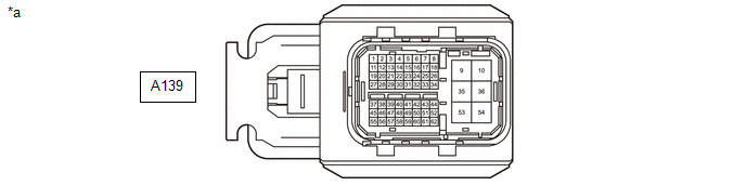
|
*a |
Front view of wire harness connector (to ECM) |
- |
- |
Bus 2 Main Lines
|
Terminal No. (Symbol) |
Terminal Description |
Condition |
Specified Condition |
|---|---|---|---|
|
A139-8 (CANH) - A139-18 (CANL) |
HIGH-level CAN bus line - LOW-level CAN bus line |
Cable disconnected from negative (-) battery terminal |
108 to 132 Ω |
|
A139-8 (CANH) - A139-10 (E1) |
HIGH-level CAN bus line - Ground |
Cable disconnected from negative (-) battery terminal |
200 Ω or higher |
|
A139-18 (CANL) - A139-10 (E1) |
LOW-level CAN bus line - Ground |
Cable disconnected from negative (-) battery terminal |
200 Ω or higher |
|
A139-8 (CANH) - A139-1 (BATT) |
HIGH-level CAN bus line - Battery positive (+) |
Cable disconnected from negative (-) battery terminal |
6 kΩ or higher |
|
A139-18 (CANL) - A139-1 (BATT) |
LOW-level CAN bus line - Battery positive (+) |
Cable disconnected from negative (-) battery terminal |
6 kΩ or higher |
Chassis Local Bus Main Lines
|
Terminal No. (Symbol) |
Terminal Description |
Condition |
Specified Condition |
|---|---|---|---|
|
A139-25 (CANU) - A139-26 (CAND) |
HIGH-level CAN bus line - LOW-level CAN bus line |
Cable disconnected from negative (-) battery terminal |
108 to 132 Ω |
|
A139-25 (CANU) - A139-10 (E1) |
HIGH-level CAN bus line - Ground |
Cable disconnected from negative (-) battery terminal |
200 Ω or higher |
|
A139-26 (CAND) - A139-10 (E1) |
LOW-level CAN bus line - Ground |
Cable disconnected from negative (-) battery terminal |
200 Ω or higher |
|
A139-25 (CANU) - A139-1 (BATT) |
HIGH-level CAN bus line - Battery positive (+) |
Cable disconnected from negative (-) battery terminal |
6 kΩ or higher |
|
A139-26 (CAND) - A139-1 (BATT) |
LOW-level CAN bus line - Battery positive (+) |
Cable disconnected from negative (-) battery terminal |
6 kΩ or higher |
25. TCM (for CVT (K120))
Refer to Terminals of ECU.
Click here
(a) Disconnect the cable from the negative (-) battery terminal.
(b) Disconnect the C80 TCM connector.
(c) Measure the resistance according to the value(s) in the table below.
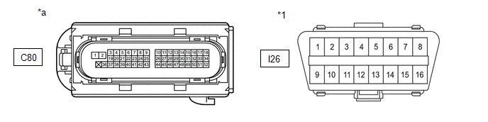
|
*1 |
DLC3 |
- |
- |
|
*a |
Front view of wire harness connector (to TCM) |
- |
- |
Standard Resistance
|
Terminal No. (Symbol) |
Terminal Description |
Condition |
Specified Condition |
|---|---|---|---|
|
C80-15 (CANH) - C80-16 (CANL) |
HIGH-level CAN bus line - LOW-level CAN bus line |
Cable disconnected from negative (-) battery terminal |
54 to 69 Ω |
|
C80-15 (CANH) - C80-2 (E1) |
HIGH-level CAN bus line - Ground |
Cable disconnected from negative (-) battery terminal |
200 Ω or higher |
|
C80-16 (CANL) - C80-2 (E1) |
LOW-level CAN bus line - Ground |
Cable disconnected from negative (-) battery terminal |
200 Ω or higher |
|
C80-15 (CANH) - I26-16 (BAT) |
HIGH-level CAN bus line - Battery positive (+) |
Cable disconnected from negative (-) battery terminal |
6 kΩ or higher |
|
C80-16 (CANL) - I26-16 (BAT) |
LOW-level CAN bus line - Battery positive (+) |
Cable disconnected from negative (-) battery terminal |
6 kΩ or higher |
26. COMBINATION METER ASSEMBLY
Refer to Terminals of ECU.
Click here
(a) Disconnect the cable from the negative (-) battery terminal.
(b) Disconnect the I4 and I5 combination meter assembly connectors.
(c) Measure the resistance according to the value(s) in the table below.
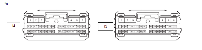
|
*a |
Front view of wire harness connector (to Combination Meter Assembly) |
- |
- |
Standard Resistance
|
Terminal No. (Symbol) |
Terminal Description |
Condition |
Specified Condition |
|---|---|---|---|
|
I5-31 (CANH) - I5-14 (CANL) |
HIGH-level CAN bus line - LOW-level CAN bus line |
Cable disconnected from negative (-) battery terminal |
108 to 132 Ω |
|
I5-31 (CANH) - I4-2 (ES) |
HIGH-level CAN bus line - Ground |
Cable disconnected from negative (-) battery terminal |
200 Ω or higher |
|
I5-14 (CANL) - I4-2 (ES) |
LOW-level CAN bus line - Ground |
Cable disconnected from negative (-) battery terminal |
200 Ω or higher |
|
I5-31 (CANH) - I5-2 (B) |
HIGH-level CAN bus line - Battery positive (+) |
Cable disconnected from negative (-) battery terminal |
6 kΩ or higher |
|
I5-14 (CANL) - I5-2 (B) |
LOW-level CAN bus line - Battery positive (+) |
Cable disconnected from negative (-) battery terminal |
6 kΩ or higher |
27. BRAKE ACTUATOR ASSEMBLY (except G16E-GTS)
Refer to Terminals of ECU.
Click here
(a) Disconnect the cable from the negative (-) battery terminal.
(b) Disconnect the A51 brake actuator assembly connector.
(c) Measure the resistance according to the value(s) in the table below.
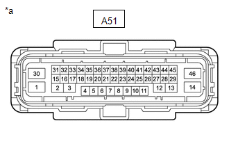
|
*a |
Front view of wire harness connector (to Brake Actuator Assembly) |
Bus 4 Branch Lines
|
Terminal No. (Symbol) |
Terminal Description |
Condition |
Specified Condition |
|---|---|---|---|
|
A51-5 (CANH) - A51-19 (CANL) |
HIGH-level CAN bus line - LOW-level CAN bus line |
Cable disconnected from negative (-) battery terminal |
54 to 69 Ω |
|
A51-5 (CANH) - A51-46 (GND1) |
HIGH-level CAN bus line - Ground |
Cable disconnected from negative (-) battery terminal |
200 Ω or higher |
|
A51-19 (CANL) - A51-46 (GND1) |
LOW-level CAN bus line - Ground |
Cable disconnected from negative (-) battery terminal |
200 Ω or higher |
|
A51-5 (CANH) - A51-30 (+BS) |
HIGH-level CAN bus line - Battery positive (+) |
Cable disconnected from negative (-) battery terminal |
6 kΩ or higher |
|
A51-19 (CANL) - A51-30 (+BS) |
LOW-level CAN bus line - Battery positive (+) |
Cable disconnected from negative (-) battery terminal |
6 kΩ or higher |
Chassis Local Bus Main Lines
|
Terminal No. (Symbol) |
Terminal Description |
Condition |
Specified Condition |
|---|---|---|---|
|
A51-11 (CA2H) - A51-25 (CA2L) |
HIGH-level CAN bus line - LOW-level CAN bus line |
Cable disconnected from negative (-) battery terminal |
108 to 132 Ω |
|
A51-11 (CA2H) - A51-46 (GND1) |
HIGH-level CAN bus line - Ground |
Cable disconnected from negative (-) battery terminal |
200 Ω or higher |
|
A51-25 (CA2L) - A51-46 (GND1) |
LOW-level CAN bus line - Ground |
Cable disconnected from negative (-) battery terminal |
200 Ω or higher |
|
A51-11 (CA2H) - A51-30 (+BS) |
HIGH-level CAN bus line - Battery positive (+) |
Cable disconnected from negative (-) battery terminal |
6 kΩ or higher |
|
A51-25 (CA2L) - A51-30 (+BS) |
LOW-level CAN bus line - Battery positive (+) |
Cable disconnected from negative (-) battery terminal |
6 kΩ or higher |
28. BRAKE ACTUATOR ASSEMBLY (for G16E-GTS)
Refer to Terminals of ECU.
Click here
(a) Disconnect the cable from the negative (-) battery terminal.
(b) Disconnect the A140 brake actuator assembly connector.
(c) Measure the resistance according to the value(s) in the table below.
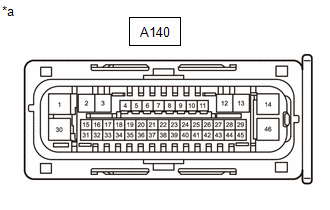
|
*a |
Front view of wire harness connector (to Brake Actuator Assembly) |
Bus 4 Branch Lines
|
Terminal No. (Symbol) |
Terminal Description |
Condition |
Specified Condition |
|---|---|---|---|
|
A140-27 (CANH) - A140-43 (CANL) |
HIGH-level CAN bus line - LOW-level CAN bus line |
Cable disconnected from negative (-) battery terminal |
54 to 69 Ω |
|
A140-27 (CANH) - A140-1 (GND1) |
HIGH-level CAN bus line - Ground |
Cable disconnected from negative (-) battery terminal |
200 Ω or higher |
|
A140-43 (CANL) - A140-1 (GND1) |
LOW-level CAN bus line - Ground |
Cable disconnected from negative (-) battery terminal |
200 Ω or higher |
|
A140-27 (CANH) - A140-14 (+BS) |
HIGH-level CAN bus line - Battery positive (+) |
Cable disconnected from negative (-) battery terminal |
6 kΩ or higher |
|
A140-43 (CANL) - A140-14 (+BS) |
LOW-level CAN bus line - Battery positive (+) |
Cable disconnected from negative (-) battery terminal |
6 kΩ or higher |
Chassis Local Bus Main Lines
|
Terminal No. (Symbol) |
Terminal Description |
Condition |
Specified Condition |
|---|---|---|---|
|
A140-16 (CA2H) - A140-17 (CA2L) |
HIGH-level CAN bus line - LOW-level CAN bus line |
Cable disconnected from negative (-) battery terminal |
108 to 132 Ω |
|
A140-16 (CA2H) - A140-1 (GND1) |
HIGH-level CAN bus line - Ground |
Cable disconnected from negative (-) battery terminal |
200 Ω or higher |
|
A140-17 (CA2L) - A140-1 (GND1) |
LOW-level CAN bus line - Ground |
Cable disconnected from negative (-) battery terminal |
200 Ω or higher |
|
A140-16 (CA2H) - A140-14 (+BS) |
HIGH-level CAN bus line - Battery positive (+) |
Cable disconnected from negative (-) battery terminal |
6 kΩ or higher |
|
A140-17 (CA2L) - A140-14 (+BS) |
LOW-level CAN bus line - Battery positive (+) |
Cable disconnected from negative (-) battery terminal |
6 kΩ or higher |
29. MAIN BODY ECU (MULTIPLEX NETWORK BODY ECU)
Refer to Terminals of ECU.
Click here
(a) Disconnect the cable from the negative (-) battery terminal.
(b) Disconnect the I85 main body ECU (multiplex network body ECU) connector.
(c) Measure the resistance according to the value(s) in the table below.
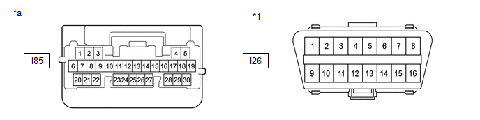
|
*1 |
DLC3 |
- |
- |
|
*a |
Front view of wire harness connector (to Main Body ECU (Multiplex Network Body ECU)) |
- |
- |
Standard Resistance
|
Terminal No. (Symbol) |
Terminal Description |
Condition |
Specified Condition |
|---|---|---|---|
|
I85-2 (CANH) - I85-1 (CANL) |
HIGH-level CAN bus line - LOW-level CAN bus line |
Cable disconnected from negative (-) battery terminal |
108 to 132 Ω |
|
I85-2 (CANH) - I26-4 (CG) |
HIGH-level CAN bus line - Ground |
Cable disconnected from negative (-) battery terminal |
200 Ω or higher |
|
I85-1 (CANL) - I26-4 (CG) |
LOW-level CAN bus line - Ground |
Cable disconnected from negative (-) battery terminal |
200 Ω or higher |
|
I85-2 (CANH) - I26-16 (BAT) |
HIGH-level CAN bus line - Battery positive (+) |
Cable disconnected from negative (-) battery terminal |
6 kΩ or higher |
|
I85-1 (CANL) - I26-16 (BAT) |
LOW-level CAN bus line - Battery positive (+) |
Cable disconnected from negative (-) battery terminal |
6 kΩ or higher |
30. CERTIFICATION ECU (SMART KEY ECU ASSEMBLY) (w/ Smart Key System)
Refer to Terminals of ECU.
Click here
(a) Disconnect the cable from the negative (-) battery terminal.
(b) Disconnect the I167 certification ECU (smart key ECU assembly) connector.
(c) Measure the resistance according to the value(s) in the table below.
Standard Resistance
|
Terminal No. (Symbol) |
Terminal Description |
Condition |
Specified Condition |
|---|---|---|---|
|
I167-1 (CANH) - I167-2 (CANL) |
HIGH-level CAN bus line - LOW-level CAN bus line |
Cable disconnected from negative (-) battery terminal |
54 to 69 Ω |
|
I167-1 (CANH) - I167-29 (E) |
HIGH-level CAN bus line - Ground |
Cable disconnected from negative (-) battery terminal |
200 Ω or higher |
|
I167-2 (CANL) - I167-29 (E) |
LOW-level CAN bus line - Ground |
Cable disconnected from negative (-) battery terminal |
200 Ω or higher |
|
I167-1 (CANH) - I167-6 (+B) |
HIGH-level CAN bus line - Battery positive (+) |
Cable disconnected from negative (-) battery terminal |
6 kΩ or higher |
|
I167-2 (CANL) - I167-6 (+B) |
LOW-level CAN bus line - Battery positive (+) |
Cable disconnected from negative (-) battery terminal |
6 kΩ or higher |
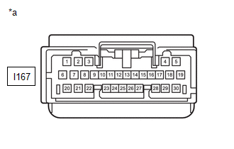
|
*a |
Front view of wire harness connector (to Certification ECU (Smart Key ECU Assembly)) |
31. POWER STEERING ECU WITH MOTOR ASSEMBLY
Refer to Terminals of ECU.
Click here
(a) Disconnect the cable from the negative (-) battery terminal.
(b) Disconnect the I21 and I42 power steering ECU with motor assembly connectors.
(c) Measure the resistance according to the value(s) in the table below.
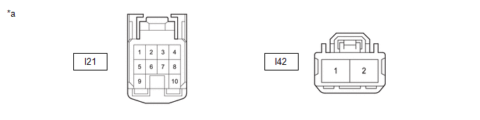
|
*a |
Front view of wire harness connector (to Power Steering ECU with Motor Assembly) |
- |
- |
Standard Resistance
|
Terminal No. (Symbol) |
Terminal Description |
Condition |
Specified Condition |
|---|---|---|---|
|
I21-7 (CANH) - I21-8 (CANL) |
HIGH-level CAN bus line - LOW-level CAN bus line |
Cable disconnected from negative (-) battery terminal |
108 to 132 Ω |
|
I21-7 (CANH) - I42-2 (PGND) |
HIGH-level CAN bus line - Ground |
Cable disconnected from negative (-) battery terminal |
200 Ω or higher |
|
I21-8 (CANL) - I42-2 (PGND) |
LOW-level CAN bus line - Ground |
Cable disconnected from negative (-) battery terminal |
200 Ω or higher |
|
I21-7 (CANH) - I42-1 (PIG) |
HIGH-level CAN bus line - Battery positive (+) |
Cable disconnected from negative (-) battery terminal |
6 kΩ or higher |
|
I21-8 (CANL) - I42-1 (PIG) |
LOW-level CAN bus line - Battery positive (+) |
Cable disconnected from negative (-) battery terminal |
6 kΩ or higher |
32. AIRBAG SENSOR ASSEMBLY
Refer to Terminals of ECU.
Click here
(a) Disconnect the cable from the negative (-) battery terminal.
(b) Disconnect the I47 airbag sensor assembly connector.
(c) Measure the resistance according to the value(s) in the table below.
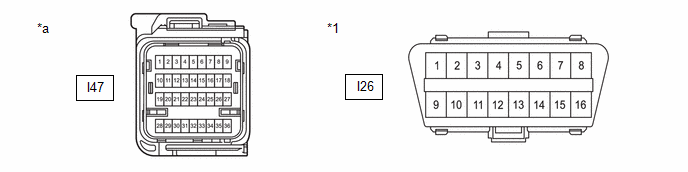
|
*1 |
DLC3 |
- |
- |
|
*a |
Front view of wire harness connector (to Airbag Sensor Assembly) |
- |
- |
Standard Resistance
|
Terminal No. (Symbol) |
Terminal Description |
Condition |
Specified Condition |
|---|---|---|---|
|
I47-26 (CAFH) - I47-27 (CAFL) |
HIGH-level CAN bus line - LOW-level CAN bus line |
Cable disconnected from negative (-) battery terminal |
54 to 69 Ω |
|
I47-26 (CAFH) - I47-33 (E1) |
HIGH-level CAN bus line - Ground |
Cable disconnected from negative (-) battery terminal |
200 Ω or higher |
|
I47-27 (CAFL) - I47-33 (E1) |
LOW-level CAN bus line - Ground |
Cable disconnected from negative (-) battery terminal |
200 Ω or higher |
|
I47-26 (CAFH) - I26-16 (BAT) |
HIGH-level CAN bus line - Battery positive (+) |
Cable disconnected from negative (-) battery terminal |
6 kΩ or higher |
|
I47-27 (CAFL) - I26-16 (BAT) |
LOW-level CAN bus line - Battery positive (+) |
Cable disconnected from negative (-) battery terminal |
6 kΩ or higher |
33. AIR CONDITIONING AMPLIFIER ASSEMBLY
Refer to Terminals of ECU.
Click here
(a) Disconnect the cable from the negative (-) battery terminal.
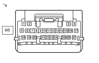
(b) Disconnect the I49 air conditioning amplifier assembly connector.
(c) Measure the resistance according to the value(s) in the table below.
|
*a |
Front view of wire harness connector (to Air Conditioning Amplifier Assembly) |
Standard Resistance
|
Terminal No. (Symbol) |
Terminal Description |
Condition |
Specified Condition |
|---|---|---|---|
|
I49-2 (CANH) - I49-1 (CANL) |
HIGH-level CAN bus line - LOW-level CAN bus line |
Cable disconnected from negative (-) battery terminal |
54 to 69 Ω |
|
I49-2 (CANH) - I49-17 (GND) |
HIGH-level CAN bus line - Ground |
Cable disconnected from negative (-) battery terminal |
200 Ω or higher |
|
I49-1 (CANL) - I49-17 (GND) |
LOW-level CAN bus line - Ground |
Cable disconnected from negative (-) battery terminal |
200 Ω or higher |
|
I49-2 (CANH) - I49-5 (B) |
HIGH-level CAN bus line - Battery positive (+) |
Cable disconnected from negative (-) battery terminal |
6 kΩ or higher |
|
I49-1 (CANL) - I49-5 (B) |
LOW-level CAN bus line - Battery positive (+) |
Cable disconnected from negative (-) battery terminal |
6 kΩ or higher |
34. BLIND SPOT MONITOR SENSOR LH (B) (w/ Blind Spot Monitor System)
Refer to Terminals of ECU.
Click here
(a) Disconnect the cable from the negative (-) battery terminal.
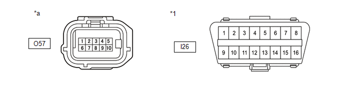
(b) Disconnect the O57 blind spot monitor sensor LH (B) connector.
(c) Measure the resistance according to the value(s) in the table below.
|
*1 |
DLC3 |
- |
- |
|
*a |
Front view of wire harness connector (to Blind Spot Monitor Sensor LH (B)) |
- |
- |
Standard Resistance
|
Terminal No. (Symbol) |
Terminal Description |
Condition |
Specified Condition |
|---|---|---|---|
|
O57-2 (CA1P) - O57-7 (CA1N) |
HIGH-level CAN bus line - LOW-level CAN bus line |
Cable disconnected from negative (-) battery terminal |
54 to 69 Ω |
|
O57-2 (CA1P) - O57-10 (BLGD) |
HIGH-level CAN bus line - Ground |
Cable disconnected from negative (-) battery terminal |
200 Ω or higher |
|
O57-7 (CA1N) - O57-10 (BLGD) |
LOW-level CAN bus line - Ground |
Cable disconnected from negative (-) battery terminal |
200 Ω or higher |
|
O57-2 (CA1P) - I26-16 (BAT) |
HIGH-level CAN bus line - Battery positive (+) |
Cable disconnected from negative (-) battery terminal |
6 kΩ or higher |
|
O57-7 (CA1N) - I26-16 (BAT) |
LOW-level CAN bus line - Battery positive (+) |
Cable disconnected from negative (-) battery terminal |
6 kΩ or higher |
35. FORWARD RECOGNITION CAMERA (w/ Front Camera System)
Refer to Terminals of ECU.
Click here
(a) Disconnect the cable from the negative (-) battery terminal.
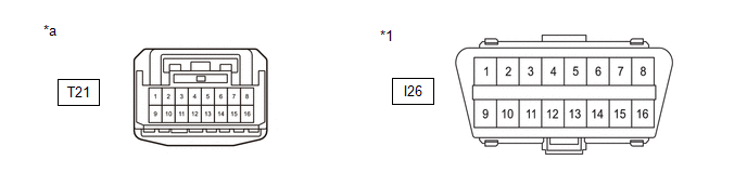
(b) Disconnect the T21 forward recognition camera connector.
(c) Measure the resistance according to the value(s) in the table below.
|
*1 |
DLC3 |
- |
- |
|
*a |
Front view of wire harness connector (to Forward Recognition Camera) |
- |
- |
Standard Resistance
|
Terminal No. (Symbol) |
Terminal Description |
Condition |
Specified Condition |
|---|---|---|---|
|
T21-2 (CA2P) - T21-1 (CA2L) |
HIGH-level CAN bus line - LOW-level CAN bus line |
Cable disconnected from negative (-) battery terminal |
108 to 132 Ω |
|
T21-2 (CA2P) - T21-13 (GND) |
HIGH-level CAN bus line - Ground |
Cable disconnected from negative (-) battery terminal |
200 Ω or higher |
|
T21-1 (CA2L) - T21-13 (GND) |
LOW-level CAN bus line - Ground |
Cable disconnected from negative (-) battery terminal |
200 Ω or higher |
|
T21-2 (CA2P) - I26-16 (BAT) |
HIGH-level CAN bus line - Battery positive (+) |
Cable disconnected from negative (-) battery terminal |
6 kΩ or higher |
|
T21-1 (CA2L) - I26-16 (BAT) |
LOW-level CAN bus line - Battery positive (+) |
Cable disconnected from negative (-) battery terminal |
6 kΩ or higher |
|
T21-10 (CA1P) - T21-9 (CA1N) |
HIGH-level CAN bus line - LOW-level CAN bus line |
Cable disconnected from negative (-) battery terminal |
108 to 132 Ω |
|
T21-10 (CA1P) - T21-13 (GND) |
HIGH-level CAN bus line - Ground |
Cable disconnected from negative (-) battery terminal |
200 Ω or higher |
|
T21-9 (CA1N) - T21-13 (GND) |
LOW-level CAN bus line - Ground |
Cable disconnected from negative (-) battery terminal |
200 Ω or higher |
|
T21-10 (CA1P) - I26-16 (BAT) |
HIGH-level CAN bus line - Battery positive (+) |
Cable disconnected from negative (-) battery terminal |
6 kΩ or higher |
|
T21-9 (CA1N) - I26-16 (BAT) |
LOW-level CAN bus line - Battery positive (+) |
Cable disconnected from negative (-) battery terminal |
6 kΩ or higher |
36. MILLIMETER WAVE RADAR SENSOR ASSEMBLY (w/ Front Camera System)
Refer to Terminals of ECU.
Click here
(a) Disconnect the cable from the negative (-) battery terminal.
(b) Disconnect the A128 millimeter wave radar sensor assembly connector.
(c) Measure the resistance according to the value(s) in the table below.
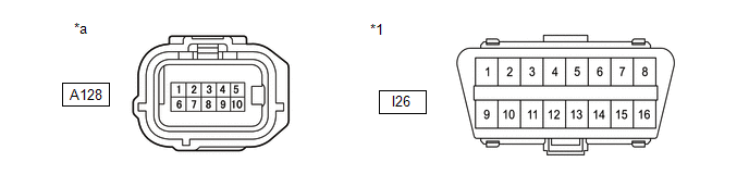
|
*1 |
DLC3 |
- |
- |
|
*a |
Front view of wire harness connector (to Millimeter Wave Radar Sensor Assembly) |
- |
- |
Standard Resistance
|
Terminal No. (Symbol) |
Terminal Description |
Condition |
Specified Condition |
|---|---|---|---|
|
A128-4 (CA2H) - A128-3 (CA2L) |
HIGH-level CAN bus line - LOW-level CAN bus line |
Cable disconnected from negative (-) battery terminal |
108 to 132 Ω |
|
A128-4 (CA2H) - A128-5 (SGND) |
HIGH-level CAN bus line - Ground |
Cable disconnected from negative (-) battery terminal |
200 Ω or higher |
|
A128-3 (CA2L) - A128-5 (SGND) |
LOW-level CAN bus line - Ground |
Cable disconnected from negative (-) battery terminal |
200 Ω or higher |
|
A128-4 (CA2H) - I26-16 (BAT) |
HIGH-level CAN bus line - Battery positive (+) |
Cable disconnected from negative (-) battery terminal |
6 kΩ or higher |
|
A128-3 (CA2L) - I26-16 (BAT) |
LOW-level CAN bus line - Battery positive (+) |
Cable disconnected from negative (-) battery terminal |
6 kΩ or higher |
|
A128-10 (CA3H) - A128-9 (CA3L) |
HIGH-level CAN bus line - LOW-level CAN bus line |
Cable disconnected from negative (-) battery terminal |
108 to 132 Ω |
|
A128-10 (CA3H) - A128-5 (SGND) |
HIGH-level CAN bus line - Ground |
Cable disconnected from negative (-) battery terminal |
200 Ω or higher |
|
A128-9 (CA3L) - A128-5 (SGND) |
LOW-level CAN bus line - Ground |
Cable disconnected from negative (-) battery terminal |
200 Ω or higher |
|
A128-10 (CA3H) - I26-16 (BAT) |
HIGH-level CAN bus line - Battery positive (+) |
Cable disconnected from negative (-) battery terminal |
6 kΩ or higher |
|
A128-9 (CA3L) - I26-16 (BAT) |
LOW-level CAN bus line - Battery positive (+) |
Cable disconnected from negative (-) battery terminal |
6 kΩ or higher |
37. DCM (TELEMATICS TRANSCEIVER) (w/ Telematics Transceiver)
Refer to Terminals of ECU.
Click here
(a) Disconnect the cable from the negative (-) battery terminal.
(b) Disconnect the I143 DCM (telematics transceiver) connector.
(c) Measure the resistance according to the value(s) in the table below.
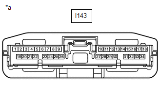
|
*a |
Front view of wire harness connector (to DCM (Telematics Transceiver)) |
Standard Resistance
|
Terminal No. (Symbol) |
Terminal Description |
Condition |
Specified Condition |
|---|---|---|---|
|
I143-25 (CANP) - I143-26 (CANN) |
HIGH-level CAN bus line - LOW-level CAN bus line |
Cable disconnected from negative (-) battery terminal |
54 to 69 Ω |
|
I143-25 (CANP) - I143-20 (E) |
HIGH-level CAN bus line - Ground |
Cable disconnected from negative (-) battery terminal |
200 Ω or higher |
|
I143-26 (CANN) - I143-20 (E) |
LOW-level CAN bus line - Ground |
Cable disconnected from negative (-) battery terminal |
200 Ω or higher |
|
I143-25 (CANP) - I143-1 (+B) |
HIGH-level CAN bus line - Battery positive (+) |
Cable disconnected from negative (-) battery terminal |
6 kΩ or higher |
|
I143-26 (CANN) - I143-1 (+B) |
LOW-level CAN bus line - Battery positive (+) |
Cable disconnected from negative (-) battery terminal |
6 kΩ or higher |
38. OPTION CONNECTOR (BUS BUFFER ECU)
(a) Disconnect the cable from the negative (-) battery terminal.
(b) Disconnect the I174 option connector (bus buffer ECU) connector.
HINT:
Disconnect any CAN compatible optional devices from the option connector.
(c) Measure the resistance according to the value(s) in the table below.
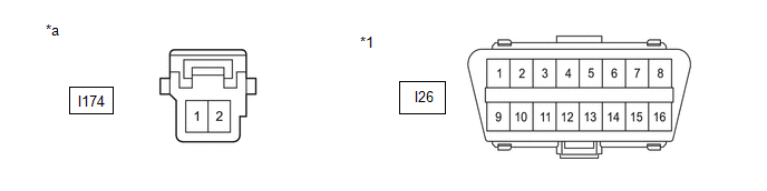
|
*1 |
DLC3 |
- |
- |
|
*a |
Front view of wire harness connector (to Option Connector (Bus Buffer ECU)) |
- |
- |
Standard Resistance
|
Terminal No. (Symbol) |
Terminal Description |
Condition |
Specified Condition |
|---|---|---|---|
|
I174-2 (CAN+) - I174-1 (CAN-) |
HIGH-level CAN bus line - LOW-level CAN bus line |
Cable disconnected from negative (-) battery terminal |
108 to 132 Ω |
|
I174-2 (CAN+) - I26-4 (CG) |
HIGH-level CAN bus line - Ground |
Cable disconnected from negative (-) battery terminal |
200 Ω or higher |
|
I174-1 (CAN-) - I26-4 (CG) |
LOW-level CAN bus line - Ground |
Cable disconnected from negative (-) battery terminal |
200 Ω or higher |
|
I174-2 (CAN+) - I26-16 (BAT) |
HIGH-level CAN bus line - Battery positive (+) |
Cable disconnected from negative (-) battery terminal |
6 kΩ or higher |
|
I174-1 (CAN-) - I26-16 (BAT) |
LOW-level CAN bus line - Battery positive (+) |
Cable disconnected from negative (-) battery terminal |
6 kΩ or higher |
39. RADIO AND DISPLAY RECEIVER ASSEMBLY (w/ Radio and Display Receiver Assembly)
Refer to Terminals of ECU.
-
for Audio and Visual System (for Single Knob Type)
Click here
-
for Navigation System (for Knobless Type)
Click here
(a) Disconnect the cable from the negative (-) battery terminal.
(b) Disconnect the I175 radio and display receiver assembly connector.
(c) Measure the resistance according to the value(s) in the table below.
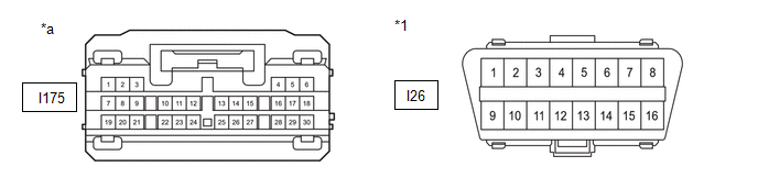
|
*1 |
DLC3 |
- |
- |
|
*a |
Front view of wire harness connector (to Radio and Display Receiver Assembly) |
- |
- |
Standard Resistance
|
Terminal No. (Symbol) |
Terminal Description |
Condition |
Specified Condition |
|---|---|---|---|
|
I175-13 (CANH) - I175-14 (CANL) |
HIGH-level CAN bus line - LOW-level CAN bus line |
Cable disconnected from negative (-) battery terminal |
54 to 69 Ω |
|
I175-13 (CANH) - I26-4 (CG) |
HIGH-level CAN bus line - Ground |
Cable disconnected from negative (-) battery terminal |
200 Ω or higher |
|
I175-14 (CANL) - I26-4 (CG) |
LOW-level CAN bus line - Ground |
Cable disconnected from negative (-) battery terminal |
200 Ω or higher |
|
I175-13 (CANH) - I26-16 (BAT) |
HIGH-level CAN bus line - Battery positive (+) |
Cable disconnected from negative (-) battery terminal |
6 kΩ or higher |
|
I175-14 (CANL) - I26-16 (BAT) |
LOW-level CAN bus line - Battery positive (+) |
Cable disconnected from negative (-) battery terminal |
6 kΩ or higher |
40. TIRE PRESSURE WARNING ECU AND RECEIVER (w/ Tire Pressure Warning System (w/ Smart Key System))
Refer to Terminals of ECU.
Click here
(a) Disconnect the cable from the negative (-) battery terminal.
(b) Disconnect the O170 tire pressure warning ECU and receiver connector.
(c) Measure the resistance according to the value(s) in the table below.
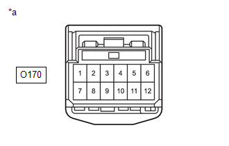
|
*a |
Front view of wire harness connector (to Tire Pressure Warning ECU and Receiver) |
Standard Resistance
|
Terminal No. (Symbol) |
Terminal Description |
Condition |
Specified Condition |
|---|---|---|---|
|
O170-9 (CANH) - O170-10 (CANL) |
HIGH-level CAN bus line - LOW-level CAN bus line |
Cable disconnected from negative (-) battery terminal |
54 to 69 Ω |
|
O170-9 (CANH) - O170-12 (GND) |
HIGH-level CAN bus line - Ground |
Cable disconnected from negative (-) battery terminal |
200 Ω or higher |
|
O170-10 (CANL) - O170-12 (GND) |
LOW-level CAN bus line - Ground |
Cable disconnected from negative (-) battery terminal |
200 Ω or higher |
|
O170-9 (CANH) - O170-7 (+B) |
HIGH-level CAN bus line - Battery positive (+) |
Cable disconnected from negative (-) battery terminal |
6 kΩ or higher |
|
O170-10 (CANL) - O170-7 (+B) |
LOW-level CAN bus line - Battery positive (+) |
Cable disconnected from negative (-) battery terminal |
6 kΩ or higher |
41. TIRE PRESSURE WARNING ECU AND RECEIVER (w/ Tire Pressure Warning System (w/o Smart Key System))
Refer to Terminals of ECU.
Click here
(a) Disconnect the cable from the negative (-) battery terminal.
(b) Disconnect the O171 tire pressure warning ECU and receiver connector.
(c) Measure the resistance according to the value(s) in the table below.
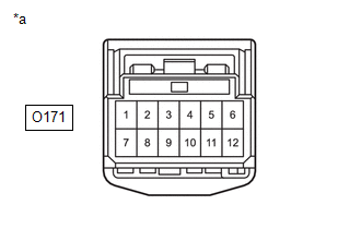
|
*a |
Front view of wire harness connector (to Tire Pressure Warning ECU and Receiver) |
Standard Resistance
|
Terminal No. (Symbol) |
Terminal Description |
Condition |
Specified Condition |
|---|---|---|---|
|
O171-9 (CANH) - O171-10 (CANL) |
HIGH-level CAN bus line - LOW-level CAN bus line |
Cable disconnected from negative (-) battery terminal |
54 to 69 Ω |
|
O171-9 (CANH) - O171-12 (GND) |
HIGH-level CAN bus line - Ground |
Cable disconnected from negative (-) battery terminal |
200 Ω or higher |
|
O171-10 (CANL) - O171-12 (GND) |
LOW-level CAN bus line - Ground |
Cable disconnected from negative (-) battery terminal |
200 Ω or higher |
|
O171-9 (CANH) - O171-7 (+B) |
HIGH-level CAN bus line - Battery positive (+) |
Cable disconnected from negative (-) battery terminal |
6 kΩ or higher |
|
O171-10 (CANL) - O171-7 (+B) |
LOW-level CAN bus line - Battery positive (+) |
Cable disconnected from negative (-) battery terminal |
6 kΩ or higher |
42. 4WD ECU ASSEMBLY (for AWD)
Refer to Terminals of ECU.
Click here
(a) Disconnect the cable from the negative (-) battery terminal.
(b) Disconnect the O177 4WD ECU assembly connector.
(c) Measure the resistance according to the value(s) in the table below.
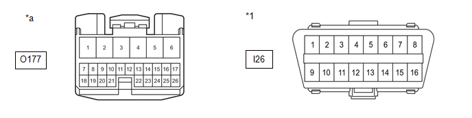
|
*1 |
DLC3 |
- |
- |
|
*a |
Front view of wire harness connector (to 4WD ECU Assembly) |
- |
- |
Standard Resistance
|
Terminal No. (Symbol) |
Terminal Description |
Condition |
Specified Condition |
|---|---|---|---|
|
O177-17 (CANH) - O177-26 (CANL) |
HIGH-level CAN bus line - LOW-level CAN bus line |
Cable disconnected from negative (-) battery terminal |
54 to 69 Ω |
|
O177-17 (CANH) - I26-4 (CG) |
HIGH-level CAN bus line - Ground |
Cable disconnected from negative (-) battery terminal |
200 Ω or higher |
|
O177-26 (CANL) - I26-4 (CG) |
LOW-level CAN bus line - Ground |
Cable disconnected from negative (-) battery terminal |
200 Ω or higher |
|
O177-17 (CANH) - I26-16 (BAT) |
HIGH-level CAN bus line - Battery positive (+) |
Cable disconnected from negative (-) battery terminal |
6 kΩ or higher |
|
O177-26 (CANL) - I26-16 (BAT) |
LOW-level CAN bus line - Battery positive (+) |
Cable disconnected from negative (-) battery terminal |
6 kΩ or higher |
43. CLEARANCE WARNING ECU ASSEMBLY (w/ Intuitive Parking Assist System)
Refer to Terminals of ECU.
Click here
(a) Disconnect the cable from the negative (-) battery terminal.
(b) Disconnect the I24 clearance warning ECU assembly connector.
(c) Measure the resistance according to the value(s) in the table below.
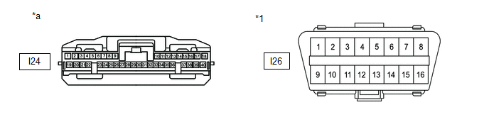
|
*1 |
DLC3 |
- |
- |
|
*a |
Front view of wire harness connector (to Clearance Warning ECU Assembly) |
- |
- |
Standard Resistance
|
Terminal No. (Symbol) |
Terminal Description |
Condition |
Specified Condition |
|---|---|---|---|
|
I24-17 (R1) - I24-18 (R2) |
HIGH-level CAN bus line - LOW-level CAN bus line |
Cable disconnected from negative (-) battery terminal |
54 to 69 Ω |
|
I24-17 (R1) - I24-31 (E) |
HIGH-level CAN bus line - Ground |
Cable disconnected from negative (-) battery terminal |
200 Ω or higher |
|
I24-18 (R2) - I24-31 (E) |
LOW-level CAN bus line - Ground |
Cable disconnected from negative (-) battery terminal |
200 Ω or higher |
|
I24-17 (R1) - I26-16 (BAT) |
HIGH-level CAN bus line - Battery positive (+) |
Cable disconnected from negative (-) battery terminal |
6 kΩ or higher |
|
I24-18 (R2) - I26-16 (BAT) |
LOW-level CAN bus line - Battery positive (+) |
Cable disconnected from negative (-) battery terminal |
6 kΩ or higher |

|

|