| Last Modified: 05-13-2024 | 6.11:8.1.0 | Doc ID: RM100000002BT1L |
| Model Year Start: 2023 | Model: GR Corolla | Prod Date Range: [03/2023 - ] |
| Title: LIGHTING (EXT): LIGHTING SYSTEM: Back-up Light Circuit; 2023 - 2025 MY Corolla Corolla Hatchback Corolla HV GR Corolla [03/2023 - ] | ||
|
Back-up Light Circuit |
DESCRIPTION
for HV Model:
- The hybrid vehicle control ECU controls the back-up lights via the BKUP LP relay.
for CVT (K121):
- The ECM controls the back-up lights via the BKUP LP relay.
WIRING DIAGRAM
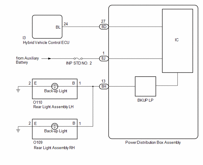
for HV Model
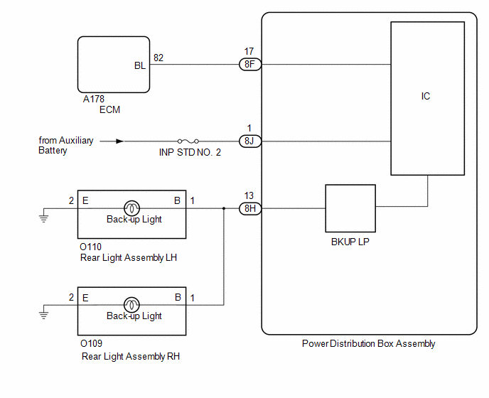
for CVT (K121)
CAUTION / NOTICE / HINT
NOTICE:
- Inspect the fuses for circuits related to this system before performing the following procedure.
-
Before replacing the hybrid vehicle control ECU, refer to Registration.
for HV Model:Click here
![2023 - 2025 MY Corolla Corolla HV [09/2022 - ]; THEFT DETERRENT / KEYLESS ENTRY: SMART KEY SYSTEM (for Start Function, HV Model): REGISTRATION](/t3Portal/stylegraphics/info.gif)
for Gasoline Model:Click here
-
When replacing the hybrid vehicle control ECU, update the ECU security key.*1
Click here
-
When replacing the ECM, update the ECU security key.*2
Click here
- *1: for HV Model
- *2: for CVT (K121)
PROCEDURE
|
1. |
CONFIRM MODEL |
(a) Choose the model to be inspected.
|
Result |
Proceed to |
|---|---|
|
for HV Model |
A |
|
for CVT (K121) |
B |
| B |

|
|

|
2. |
READ VALUE USING GTS |
(a) Turn the ignition switch to ON.
(b) Move the shift lever to R.
(c) Read the Data List according to the display on the GTS.
Body Electrical > Power Distribution Box > Data List
|
Tester Display |
Measurement Item |
Normal Condition |
Reference Value |
Diagnostic Note |
|---|---|---|---|---|
|
Back-up Light Fuse Shut Off Status |
Back-up light fuse shut off status |
OFF or ON |
OFF: Fuse has no shut off history ON: Fuse has shut off history |
- |
Body Electrical > Power Distribution Box > Data List
|
Tester Display |
|---|
|
Back-up Light Fuse Shut Off Status |
OK:
The Data List value displays "OFF".
| NG |
|
|
|
3. |
READ VALUE USING GTS |
(a) Read the Data List according to the display on the GTS.
Body Electrical > Power Distribution Box > Data List
|
Tester Display |
Measurement Item |
Normal Condition |
Reference Value |
Diagnostic Note |
|---|---|---|---|---|
|
Back-up Light Input Signal |
Back-up light input |
OFF or ON |
OFF: Shift lever in any position other than R ON: Shift lever in R |
- |
Body Electrical > Power Distribution Box > Data List
|
Tester Display |
|---|
|
Back-up Light Input Signal |
OK:
Display changes according to shift lever operation.
| NG |
|
|
|
4. |
CHECK HARNESS AND CONNECTOR (POWER SOURCE - POWER DISTRIBUTION BOX ASSEMBLY) |
(a) Disconnect the 8J power distribution box assembly connector.
(b) Measure the voltage according to the value(s) in the table below.
Standard Voltage:
|
Tester Connection |
Condition |
Specified Condition |
|---|---|---|
|
8J-1 - Body ground |
Ignition switch off |
11 to 14 V |
| NG |
|
REPAIR OR REPLACE HARNESS OR CONNECTOR |
|
|
5. |
CHECK HARNESS AND CONNECTOR (REAR LIGHT ASSEMBLY - POWER DISTRIBUTION BOX ASSEMBLY) |
(a) Disconnect the O110 rear light assembly LH connector.
(b) Disconnect the O109 rear light assembly RH connector.
(c) Disconnect the 8H power distribution box assembly connector.
(d) Measure the resistance according to the value(s) in the table below.
Standard Resistance:
|
Tester Connection |
Condition |
Specified Condition |
|---|---|---|
|
O110-1 (B) - 8H-13 |
Always |
Below 1 Ω |
|
O109-1 (B) - 8H-13 |
Always |
Below 1 Ω |
| NG |
|
REPAIR OR REPLACE HARNESS OR CONNECTOR |
|
|
6. |
CHECK HARNESS AND CONNECTOR (BAREAR LIGHT ASSEMBLY - BODY GROUND) |
(a) Measure the resistance according to the value(s) in the table below.
Standard Resistance:
|
Tester Connection |
Condition |
Specified Condition |
|---|---|---|
|
O110-2 (E) - Body ground |
Always |
Below 1 Ω |
|
O109-2 (E) - Body ground |
Always |
Below 1 Ω |
| OK |
|
| NG |
|
REPAIR OR REPLACE HARNESS OR CONNECTOR |
|
7. |
CHECK HARNESS AND CONNECTOR (HYBRID VEHICLE CONTROL ECU - POWER DISTRIBUTION BOX ASSEMBLY) |
(a) Disconnect the I3 hybrid vehicle control ECU connector.
(b) Disconnect the 8D power distribution box assembly connector.
(c) Measure the resistance according to the value(s) in the table below.
Standard Resistance:
|
Tester Connection |
Condition |
Specified Condition |
|---|---|---|
|
I3-24 (BL) - 8D-27 |
Always |
Below 1 Ω |
|
I3-24 (BL) or 8D-27 - Body ground |
Always |
10 kΩ or higher |
| NG |
|
REPAIR OR REPLACE HARNESS OR CONNECTOR |
|
|
8. |
CHECK HYBRID VEHICLE CONTROL ECU (OUTPUT VOLTAGE) |
|
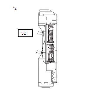
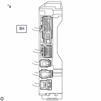
*a |
Component with harness connected (Power Distribution Box Assembly) |
(a) Connect the I3 hybrid vehicle control ECU connector.
(b) Connect the 8D power distribution box assembly connector.
(c) Measure the voltage according to the value(s) in the table below.
Standard Voltage:
|
Tester Connection |
Condition |
Specified Condition |
|---|---|---|
|
8D-27 - Body ground |
Ignition switch ON, reverse (R) not selected |
Below 1 V |
|
8D-27 - Body ground |
Ignition switch ON, reverse (R) selected |
11 to 14 V |
| OK |
|
| NG |
|
|
9. |
CHECK REAR LIGHT ASSEMBLY LH |
(a) Disconnect the O110 rear light assembly LH connector.
(b) Turn the ignition switch to ON.
(c) Move the shift lever to R.
(d) Read the Data List according to the display on the GTS.
Body Electrical > Power Distribution Box > Data List
|
Tester Display |
Measurement Item |
Normal Condition |
Reference Value |
Diagnostic Note |
|---|---|---|---|---|
|
Back-up Light Fuse Shut Off Status |
Back-up light fuse shut off status |
OFF or ON |
OFF: Fuse has no shut off history ON: Fuse has shut off history |
- |
Body Electrical > Power Distribution Box > Data List
|
Tester Display |
|---|
|
Back-up Light Fuse Shut Off Status |
OK:
The Data List value displays "OFF".
| OK |
|
|
|
10. |
CHECK REAR LIGHT ASSEMBLY RH |
(a) Disconnect the O109 rear light assembly RH connector.
(b) Turn the ignition switch to ON.
(c) Move the shift lever to R.
(d) Read the Data List according to the display on the GTS.
Body Electrical > Power Distribution Box > Data List
|
Tester Display |
Measurement Item |
Normal Condition |
Reference Value |
Diagnostic Note |
|---|---|---|---|---|
|
Back-up Light Fuse Shut Off Status |
Back-up light fuse shut off status |
OFF or ON |
OFF: Fuse has no shut off history ON: Fuse has shut off history |
- |
Body Electrical > Power Distribution Box > Data List
|
Tester Display |
|---|
|
Back-up Light Fuse Shut Off Status |
OK:
The Data List value displays "OFF".
| OK |
|
|
|
11. |
CHECK HARNESS AND CONNECTOR (REAR LIGHT ASSEMBLY - POWER DISTRIBUTION BOX ASSEMBLY) |
(a) Disconnect the 8H power distribution box assembly connector.
(b) Measure the resistance according to the value(s) in the table below.
Standard Resistance:
|
Tester Connection |
Condition |
Specified Condition |
|---|---|---|
|
O110-1 (B), O109-1 (B) or 8H-13 - Body ground |
Always |
10 kΩ or higher |
| OK |
|
| NG |
|
REPAIR OR REPLACE HARNESS OR CONNECTOR |
|
12. |
CHECK FOR DTC |
(a) Check if SFI system DTCs are output.
Powertrain > Engine > Trouble Codes
|
Result |
Proceed to |
|---|---|
|
DTCs are not output |
A |
|
DTCs are output |
B |
| B |
|
|
|
13. |
CHECK HARNESS AND CONNECTOR (ECM - POWER DISTRIBUTION BOX ASSEMBLY) |
(a) Disconnect the 8F power distribution box assembly connector.
(b) Disconnect the A178 ECM connector.
(c) Measure the resistance according to the value(s) in the table below.
Standard Resistance:
|
Tester Connection |
Condition |
Specified Condition |
|---|---|---|
|
A178-82 (BL) - 8F-17 |
Always |
Below 1 Ω |
|
A178-82 (BL) or 8F-17 - Body ground |
Always |
10 kΩ or higher |
| NG |
|
REPAIR OR REPLACE HARNESS OR CONNECTOR |
|
|
14. |
CHECK ECM (OUTPUT VOLTAGE) |
|
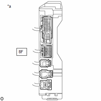
*a |
Component with harness connected (Power Distribution Box Assembly) |
(a) Measure the voltage according to the value(s) in the table below.
Standard Voltage:
|
Tester Connection |
Condition |
Specified Condition |
|---|---|---|
|
8F-17 - Body ground |
Ignition switch ON, shift lever not in R |
Below 1 V |
|
8F-17 - Body ground |
Ignition switch on (IG), shift lever in R |
11 to 14 V |
| NG |
|
|
|
15. |
INSPECT POWER DISTRIBUTION BOX ASSEMBLY (OUTPUT VOLTAGE) |
|
*a |
Component with harness connected (Power Distribution Box Assembly) |
(a) Measure the voltage according to the value(s) in the table below.
Standard Voltage:
|
Tester Connection |
Condition |
Specified Condition |
|---|---|---|
|
8H-13 - Body ground |
Ignition switch ON, shift lever not in R |
Below 1 V |
|
8H-13 - Body ground |
Ignition switch ON, shift lever in R |
11 to 14 V |
| OK |
|
REPAIR OR REPLACE HARNESS OR CONNECTOR |
| NG |
|
|
|
|