|
Last Modified: 05-13-2024 |
6.11:8.1.0 |
Doc ID: RM100000002BENP |
|
Model Year Start: 2023 |
Model: GR Corolla |
Prod Date Range: [03/2023 -
] |
|
Title: THEFT DETERRENT / KEYLESS ENTRY: SMART KEY SYSTEM (for Start Function, Gasoline Model): Engine does not Start; 2023 - 2025 MY Corolla Corolla Hatchback GR Corolla [03/2023 - ] |
DESCRIPTION
except Manual Transaxle
-
When the electrical key transmitter sub-assembly is in the cabin and the engine switch is pressed, the certification ECU (smart key ECU assembly) receives a signal and changes the power source mode. Additionally, when the shift position is in P and the brake pedal is depressed, the engine can be started by pressing the engine switch. If the steering is unlocked, the engine can also be started by pressing the engine switch with the shift position in N and the brake pedal depressed.
Related Data List and Active Test Items
|
Problem Symptom
|
Data List and Active Test
|
|
Engine does not start
|
Power Source Control
-
Stop Light Switch
-
Shift P Signal
-
Neutral SW/ Clutch SW*
-
Starter Relay Driving Request (Starting Control)
-
Starter Relay
-
Power Supply Condition
Smart Key
-
Immobiliser
-
Start Request
-
L Code Check
-
S Code Check
|
-
*: for M20A-FKS (except K121 CVT)
for Manual Transaxle
-
When the electrical key transmitter sub-assembly is in the cabin and the engine switch is pressed, the certification ECU (smart key ECU assembly) receives a signal and changes the power source mode. Additionally, when the clutch pedal is depressed, the engine can be started by pressing the engine switch.
Related Data List and Active Test Items
|
Problem Symptom
|
Data List and Active Test
|
|
Engine does not start
|
Power Source Control
-
Neutral SW/ Clutch SW
-
Starter Relay Driving Request (Starting Control)
-
Starter Relay
-
Power Supply Condition
Smart Key
-
Immobiliser
-
Start Request
-
L Code Check
-
S Code Check
|
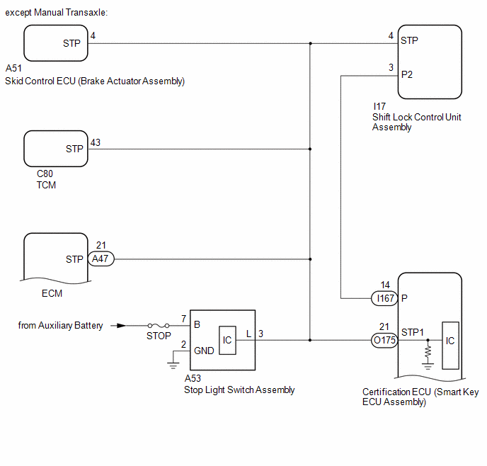
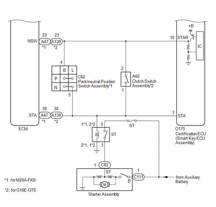
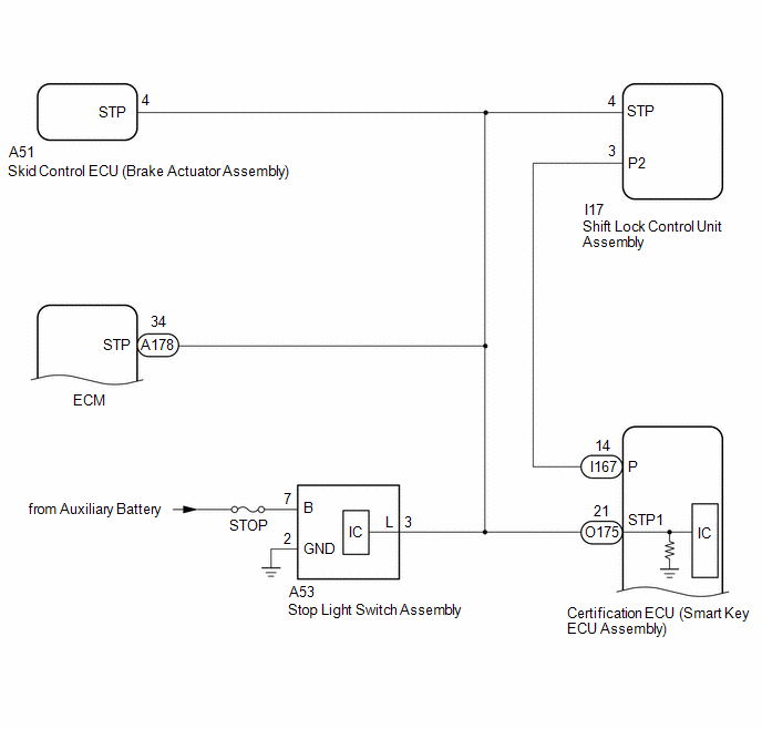
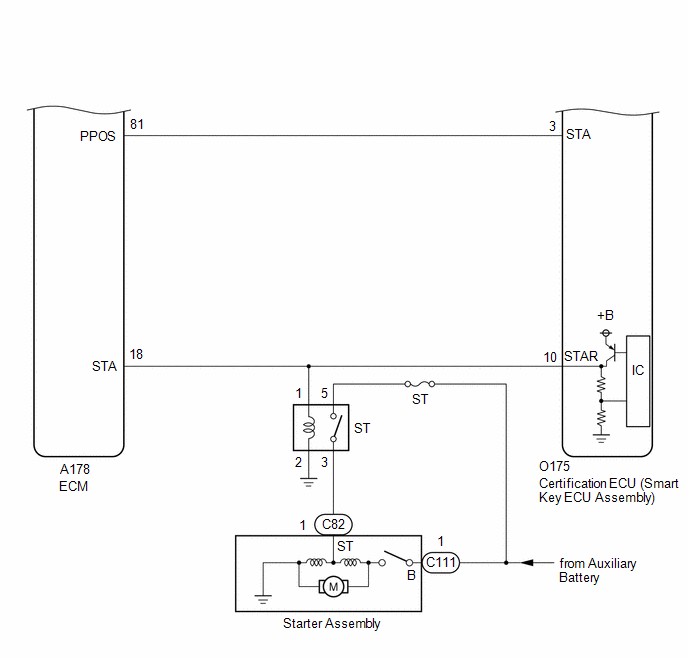
WIRING DIAGRAM
except K121 CVT
for K121 CVT
CAUTION / NOTICE / HINT
HINT:
-
If the ignition switch is changed from ON to ACC with the shift position in any position other than P, and then the shift position is moved to P and the engine switch is pressed with the brake pedal depressed, the ignition switch will turn off.*
-
If the brake pedal is repeatedly depressed while the engine is stopped, the brake booster pressure will be released and the force required to depress the brake pedal to illuminate the stop lights will increase.*
-
*: except Manual Transaxle
PROCEDURE
|
1.
|
CHECK WHETHER ENGINE STARTS
|
(a) Using an electrical key transmitter sub-assembly which is registered to the vehicle, turn the ignition switch to ON.
(b) Check that the engine can be started 5 seconds after the ignition switch turned to ON.
OK:
Engine starts normally.
|
NG
|

|
|
|
2.
|
CHECK SECURITY INDICATOR LIGHT (IMMOBILISER FUNCTION UNSET)
|
(a) Get into the vehicle while carrying an electrical key transmitter sub-assembly.
(b) Move the shift position to P.*1
(c) Press the engine switch with the brake pedal released and check that the security indicator light changes from blinking to off at the same time that the power source mode changes to ACC.*1
(d) Press the engine switch with the clutch pedal released and check that the security indicator light changes from blinking to off at the same time that the power source mode changes to ACC.*2
OK:
The security indicator light changes from blinking to off at the same time that the power source mode changes to ACC.
HINT:
The immobiliser function can be determined to be operating correctly if the security indicator light changes from blinking to off at the same time that the power source mode changes to ACC.
-
*1: except Manual Transaxle
-
*2: for Manual Transaxle
|
OK
|
|
|
|
(a) Using the GTS, check if LIN communication DTC B278588 and B278987 are output.
Body Electrical > Smart Key > Trouble Codes
OK:
DTC B278588 and B278987 are not output.
|
OK
|
|
|
|
|
4.
|
CHECK ENGINE CRANKING OPERATION
|
(a) Get into the vehicle while carrying an electrical key transmitter sub-assembly.
(b) Move the shift position to P.*1
(c) Depressed the brake pedal.*1
(d) Depressed the clutch pedal.*2
-
*1: except Manual Transaxle
-
*2: for Manual Transaxle
(e) Check that the key indicator display is displayed on the multi-information display in the combination meter assembly, and then press the engine switch and check that the engine cranks.
|
Result
|
Proceed to
|
|
Engine cranks and initial combustion occurs
|
A
|
|
Engine cranks but initial combustion does not occur
|
B
|
|
Engine does not crank
|
C
|
| B |

|
GO TO SFI SYSTEM
for M20A-FKS: Click here
![2019 - 2025 MY Corolla Corolla Hatchback [06/2018 - ]; M20A-FKS (ENGINE CONTROL): SFI SYSTEM: HOW TO PROCEED WITH TROUBLESHOOTING](/t3Portal/stylegraphics/info.gif)
for G16E-GTS: Click here
|
|
C
|
|
|
|
|
5.
|
CHECK ENGINE SWITCH CONDITION
|
(a) Get into the vehicle while carrying an electrical key transmitter sub-assembly.
(b) Move the shift position to P.*1
(c) With the brake pedal released, check that pressing the engine switch causes the power source mode to change.*1
(d) With the clutch pedal released, check that pressing the engine switch causes the power source mode to change.*2
-
*1: except Manual Transaxle
-
*2: for Manual Transaxle
|
Result
|
Proceed to
|
|
Power source mode changes : Off → ACC → ON → off
(except Manual Transaxle (except K121 CVT))
|
A
|
|
Power source mode changes : Off → ACC → ON → off
(for Manual Transaxle)
|
B
|
|
Power source mode changes : Off → ACC → ON → off
(except Manual Transaxle (for K121 CVT))
|
C
|
|
Power source mode does not change to ACC or ON
|
D
|
|
Power source mode changes to ON but not to ACC
|
E
|
|
Power source mode changes to ACC but not to ON
|
F
|
|
A
|
|
|
|
|
6.
|
READ VALUE USING GTS (STOP LIGHT SWITCH1)
|
(a) Read the Data List according to the display on the GTS.
Body Electrical > Power Source Control > Data List
|
Tester Display
|
Measurement Item
|
Range
|
Normal Condition
|
Diagnostic Note
|
|
Stop Light Switch
|
State of brake pedal
|
OFF or ON
|
OFF: Brake pedal released
ON: Brake pedal depressed
|
-
Use this item to determine if the stop light switch assembly is malfunctioning.
-
The engine cannot be started when this item is OFF.
-
If the stop light switch assembly is malfunctioning, the engine can be started by pressing and holding the engine switch for a certain period of time.
|
Body Electrical > Power Source Control > Data List
|
Tester Display
|
|
Stop Light Switch
|
OK:
The GTS display changes correctly in response to the brake pedal operation.
|
OK
|
|
|
|
|
7.
|
READ VALUE USING GTS (SHIFT P SIGNAL)
|
(a) Move the shift position to P.
(b) Read the Data List according to the display on the GTS.
Body Electrical > Power Source Control > Data List
|
Tester Display
|
Measurement Item
|
Range
|
Normal Condition
|
Diagnostic Note
|
|
Shift P Signal
|
Shift position P
|
OFF or ON
|
OFF: Shift position not in P
ON: Shift position in P
|
-
Use this item to determine if the shift position switch is malfunctioning.
-
The engine cannot be started when this item is OFF.
|
Body Electrical > Power Source Control > Data List
|
Tester Display
|
|
Shift P Signal
|
OK:
ON is displayed on the GTS.
|
OK
|
|
|
|
|
8.
|
READ VALUE USING GTS (NEUTRAL SW/ CLUTCH SW, SHIFT P/N (STARTING CONTROL))
|
(a) Read the Data List according to the display on the GTS.
Body Electrical > Power Source Control > Data List
|
Tester Display
|
Measurement Item
|
Range
|
Normal Condition
|
Diagnostic Note
|
|
Neutral Switch / Clutch Switch
|
Shift position (P and N)
|
OFF or ON
|
OFF: Shift position in any position other than P or N
ON: Shift position in P or N
|
-
Use this item to determine if the park/neutral position switch assembly is malfunctioning.
-
When the engine cannot be started due to a park/neutral position switch assembly malfunction, OFF is displayed.
|
Body Electrical > Power Source Control > Data List
|
Tester Display
|
|
Neutral Switch / Clutch Switch
|
Body Electrical > Power Source Control > Data List
|
Tester Display
|
Measurement Item
|
Range
|
Normal Condition
|
Diagnostic Note
|
|
Shift P/N (Starting Control)
|
Park/Neutral position switch status
|
OFF or ON
|
OFF: Shift position in any position other than P or N
ON: Shift position in P or N
|
When OFF is displayed, the engine will not crank.
|
Body Electrical > Power Source Control > Data List
|
Tester Display
|
|
Shift P/N (Starting Control)
|
OK:
The GTS display changes correctly in response to the shift position.
|
OK
|
|
|
|
|
9.
|
READ VALUE USING GTS (POWER SUPPLY CONDITION)
|
(a) Read the Data List according to the display on the GTS.
Body Electrical > Power Source Control > Data List
|
Tester Display
|
Measurement Item
|
Range
|
Normal Condition
|
Diagnostic Note
|
|
Power Supply Condition
|
Power supply state
|
OFF, ACC ON, IGR ON, IGP ON or Starter ON
|
OFF: Ignition switch off
ACC ON: Ignition switch ACC
IGR ON: Ignition switch ON
IGP ON: Ignition switch ON
Starter ON: Sending engine start request signal
|
-
|
Body Electrical > Power Source Control > Data List
|
Tester Display
|
|
Power Supply Condition
|
NOTICE:
Check that the key indicator display is displayed on the multi-information display in the combination meter assembly, and then press the engine switch.
OK:
The GTS display changes correctly in response to the engine switch operation.
|
OK
|
|
|
|
|
10.
|
READ VALUE USING GTS (STARTER RELAY DRIVING REQUEST (STARTING CONTROL))
|
(a) Get into the vehicle while carrying an electrical key transmitter sub-assembly.
(b) Move the shift position to P.
(c) According to the display on the GTS, read the Data List while pressing the engine switch with the brake pedal depressed.
Body Electrical > Power Source Control > Data List
|
Tester Display
|
Measurement Item
|
Range
|
Normal Condition
|
Diagnostic Note
|
|
Starter Relay Driving Request (Starting Control)
|
Engine start request signal status
|
OFF or ON
|
OFF: The engine switch is not pressed
ON: With the shift position in P and the brake pedal depressed, the engine switch is pressed and held
|
-
When the engine cannot be started due to a start request signal malfunction, OFF is displayed.
-
When the engine switch is pressed, the duration of time that ON is displayed will be extremely short. As such, the engine switch needs to be pressed and held for a certain period of time.
|
Body Electrical > Power Source Control > Data List
|
Tester Display
|
|
Starter Relay Driving Request (Starting Control)
|
OK:
The GTS display changes.
|
OK
|
|
|
|
|
11.
|
CHECK HARNESS AND CONNECTOR (CERTIFICATION ECU (SMART KEY ECU ASSEMBLY) - ST RELAY)
|
|
(a) Measure the voltage according to the value(s) in the table below.
Standard Voltage:
|
Tester Connection
|
Condition
|
Specified Condition
|
|
No. 1 engine room relay block and No. 1 junction block assembly ST relay terminal 1 - Body ground
|
Engine switch pressed and held with brake pedal depressed (starter on) → Approximately 1 second after engine switch released (starter off)
|
6 V or higher* → 1.0 V or less
|
HINT:
*: While the engine is cranking, the auxiliary battery voltage may drop to approximately 6 V.
|

|
|
*1
|
No. 1 Engine Room Relay Block and No. 1 Junction Block Assembly
(ST Relay Holder)
|
|
|
|
OK
|
|
|
|
|
12.
|
CHECK HARNESS AND CONNECTOR (ST RELAY - AUXILIARY BATTERY AND BODY GROUND)
|
|
(a) Measure the resistance according to the value(s) in the table below.
Standard Resistance:
|
Tester Connection
|
Condition
|
Specified Condition
|
|
No. 1 engine room relay block and No. 1 junction block assembly ST relay terminal 2 - Body ground
|
Always
|
Below 1 Ω
|
|
|
|
|
*1
|
No. 1 Engine Room Relay Block and No. 1 Junction Block Assembly
(ST Relay Holder)
|
|
|
(b) Measure the voltage according to the value(s) in the table below.
Standard Voltage:
|
Tester Connection
|
Condition
|
Specified Condition
|
|
No. 1 engine room relay block and No. 1 junction block assembly ST relay terminal 5 - Body ground
|
Always
|
11 to 14 V
|
| NG |
|
REPAIR OR REPLACE HARNESS OR CONNECTOR
|
|
OK
|
|
|
|
Click here
|
OK
|
|
|
|
|
14.
|
CHECK HARNESS AND CONNECTOR (STARTER ASSEMBLY - ST RELAY)
|
(a) Disconnect the C82 starter assembly connector.
(b) Measure the resistance according to the value(s) in the table below.
Standard Resistance:
|
Tester Connection
|
Condition
|
Specified Condition
|
|
No. 1 engine room relay block and No. 1 junction block assembly ST relay terminal 3 - C82-1 (ST)
|
Always
|
Below 1 Ω
|
|
No. 1 engine room relay block and No. 1 junction block assembly ST relay terminal 3 or C82-1 (ST) - Other terminals and body ground
|
Always
|
10 kΩ or higher
|
| NG |
|
REPAIR OR REPLACE HARNESS OR CONNECTOR
|
|
OK
|
|
|
|
|
15.
|
CHECK HARNESS AND CONNECTOR (STARTER ASSEMBLY - AUXILIARY BATTERY)
|
(a) Disconnect the C111 starter assembly connector.
(b) Measure the voltage according to the value(s) in the table below.
Standard Voltage:
|
Tester Connection
|
Condition
|
Specified Condition
|
|
C111-1 (B) - Body ground
|
Always
|
11 to 14 V
|
| OK |
|
REPLACE STARTER ASSEMBLY
for M20A-FKS: Click here
for G16E-GTS: Click here
|
| NG |
|
REPAIR OR REPLACE HARNESS OR CONNECTOR
|
|
16.
|
CHECK HARNESS AND CONNECTOR (PARK/NEUTRAL POSITION SWITCH ASSEMBLY - ST RELAY)
|
(a) Disconnect the C62 park/neutral position switch assembly connector.
(b) Measure the resistance according to the value(s) in the table below.
Standard Resistance:
|
Tester Connection
|
Condition
|
Specified Condition
|
|
C62-5 (L) - No. 1 engine room relay block and No. 1 junction block assembly ST relay terminal 1
|
Always
|
Below 1 Ω
|
|
C62-5 (L) or No. 1 engine room relay block and No. 1 junction block assembly ST relay terminal 1 - Other terminals and body ground
|
Always
|
10 kΩ or higher
|
| NG |
|
REPAIR OR REPLACE HARNESS OR CONNECTOR
|
|
17.
|
CHECK SECURITY INDICATOR LIGHT (IMMOBILISER FUNCTION UNSET)
|
(a) Get into the vehicle while carrying an electrical key transmitter sub-assembly.
(b) Move the shift lever to P.
(c) Press the engine switch with the brake pedal released and check that the security indicator light changes from blinking to off at the same time that the power source mode changes to ACC.
OK:
The security indicator light changes from blinking to off at the same time that the power source mode changes to ACC.
HINT:
The immobiliser function can be determined to be operating correctly if the security indicator light changes from blinking to off at the same time that the power source mode changes to ACC.
|
18.
|
READ VALUE USING GTS (NEUTRAL SW/ CLUTCH SW)
|
(a) Disconnect the A47 ECM connector.
(b) Read the Data List according to the display on the GTS.
Body Electrical > Power Source Control > Data List
|
Tester Display
|
Measurement Item
|
Range
|
Normal Condition
|
Diagnostic Note
|
|
Neutral Switch / Clutch Switch
|
Shift position (P and N)
|
OFF or ON
|
OFF: Shift position in any position other than P or N
ON: Shift position in P or N
|
-
Use this item to determine if the park/neutral position switch assembly is malfunctioning.
-
When the engine cannot be started due to a park/neutral position switch assembly malfunction, OFF is displayed.
|
Body Electrical > Power Source Control > Data List
|
Tester Display
|
|
Neutral Switch / Clutch Switch
|
OK:
The GTS display changes correctly in response to the shift position.
|
NG
|
|
|
|
|
19.
|
INSPECT PARK/NEUTRAL POSITION SWITCH ASSEMBLY
|
Click here
| NG |
|
REPLACE PARK/NEUTRAL POSITION SWITCH ASSEMBLY
|
|
OK
|
|
|
|
|
20.
|
CHECK HARNESS AND CONNECTOR (CERTIFICATION ECU (SMART KEY ECU ASSEMBLY) - PARK/NEUTRAL POSITION SWITCH ASSEMBLY)
|
(a) Disconnect the O175 certification ECU (smart key ECU assembly) connector.
(b) Disconnect the C62 park/neutral position switch assembly connector.
(c) Disconnect the A47 ECM connector.
(d) Remove the ST relay.
(e) Measure the resistance according to the value(s) in the table below.
Standard Resistance:
|
Tester Connection
|
Condition
|
Specified Condition
|
|
O175-3 (STA) - C62-5 (L)
|
Always
|
Below 1 Ω
|
|
O175-3 (STA) - A47-30 (STA)
|
Always
|
Below 1 Ω
|
|
O175-3 (STA) - No. 1 engine room relay block and No. 1 junction block assembly ST relay terminal 1
|
Always
|
Below 1 Ω
|
|
O175-10 (STAR) - C62-4 (B)
|
Always
|
Below 1 Ω
|
|
O175-10 (STAR) - A47-23 (NSW)
|
Always
|
Below 1 Ω
|
|
O175-3 (STA), C62-5 (L), A47-30 (STA) or No. 1 engine room relay block and No. 1 junction block assembly ST relay terminal 1 - Other terminals and body ground
|
Always
|
10 kΩ or higher
|
|
O175-10 (STAR), C62-4 (B) or A47-23 (NSW) - Other terminals and body ground
|
Always
|
10 kΩ or higher
|
| NG |
|
REPAIR OR REPLACE HARNESS OR CONNECTOR
|
|
OK
|
|
|
|
|
21.
|
CHECK CERTIFICATION ECU (SMART KEY ECU ASSEMBLY)
|
(a) Connect the O175 certification ECU (smart key ECU assembly) connector.
(b) Measure the voltage according to the value(s) in the table below.
Standard Voltage:
|
Tester Connection
|
Condition
|
Specified Condition
|
|
O175-10 (STAR) - Body ground
|
Engine switch pressed and held with brake pedal depressed (starter on) → Approximately 1 second after engine switch released (starter off)
|
6 V or higher* → 1.0 V or less
|
HINT:
*: While the engine is cranking, the auxiliary battery voltage may drop to approximately 6 V.
|
OK
|
|
|
|
for M20A-FKS: Click here
for G16E-GTS: Click here
| NG |
|
REPLACE ST RELAY
for M20A-FKS: Click here
for G16E-GTS: Click here
|
|
23.
|
CHECK SHIFT LOCK CONTROL UNIT ASSEMBLY
|
(a) Measure the resistance according to the value(s) in the table below.
Standard Resistance:
|
Tester Connection
|
Condition
|
Specified Condition
|
|
I167-14 (P) - Body ground
|
Shift position in P → Shift position not in P
|
30 kΩ or higher → Below 200 Ω
|
|
NG
|
|
|
|
|
24.
|
CHECK HARNESS AND CONNECTOR (CERTIFICATION ECU (SMART KEY ECU ASSEMBLY) - SHIFT LOCK CONTROL UNIT ASSEMBLY)
|
(a) Disconnect the I167 certification ECU (smart key ECU assembly) connector.
(b) Disconnect the I17 shift lock control unit assembly connector.
(c) Measure the resistance according to the value(s) in the table below.
Standard Resistance:
|
Tester Connection
|
Condition
|
Specified Condition
|
|
I167-14 (P) - I17-3 (P2)
|
Always
|
Below 1 Ω
|
|
I167-14 (P) or I17-3 (P2) - Other terminals and body ground
|
Always
|
10 kΩ or higher
|
| NG |
|
REPAIR OR REPLACE HARNESS OR CONNECTOR
|
|
25.
|
CHECK HARNESS AND CONNECTOR (STOP LIGHT SWITCH ASSEMBLY - AUXILIARY BATTERY AND GROUND)
|
(a) Disconnect the A53 stop light switch assembly connector.
|
(b) Measure the voltage according to the value(s) in the table below.
Standard Voltage:
|
Tester Connection
|
Condition
|
Specified Condition
|
|
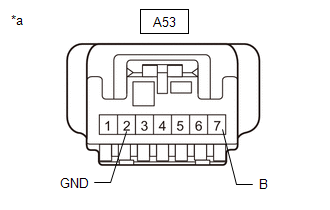
A53-7 (B) - Body ground
|
Always
|
11 to 14 V
|
|
|
|
*a
|
Front view of wire harness connector
(to Stop Light Switch Assembly)
|
|
|
(c) Measure the resistance according to the value(s) in the table below.
Standard Resistance:
|
Tester Connection
|
Condition
|
Specified Condition
|
|
A53-2 (GND) - Body ground
|
Always
|
Below 1 Ω
|
| NG |
|
REPAIR OR REPLACE HARNESS OR CONNECTOR
|
|
OK
|
|
|
|
|
26.
|
INSPECT STOP LIGHT SWITCH ASSEMBLY
|
Click here
|
OK
|
|
|
|
|
27.
|
CHECK HARNESS AND CONNECTOR (CERTIFICATION ECU (SMART KEY ECU ASSEMBLY) - STOP LIGHT SWITCH ASSEMBLY)
|
(a) Disconnect the O175 certification ECU (smart key ECU assembly) connector.
(b) Disconnect the A47 ECM connector.
(c) Disconnect the A51 skid control ECU (brake actuator assembly) connector.
(d) Disconnect the I17 shift lock control unit assembly connector.
(e) Disconnect the C80 TCM connector.
(f) Measure the resistance according to the value(s) in the table below.
Standard Resistance:
|
Tester Connection
|
Condition
|
Specified Condition
|
|
O175-21 (STP1) - A53-3 (L)
|
Always
|
Below 1 Ω
|
|
O175-21 (STP1) or A53-3 (L) - Other terminals and body ground
|
Always
|
10 kΩ or higher
|
| NG |
|
REPAIR OR REPLACE HARNESS OR CONNECTOR
|
|
28.
|
READ VALUE USING GTS (NEUTRAL SWITCH / CLUTCH SWITCH)
|
(a) Read the Data List according to the display on the GTS.
Body Electrical > Power Source Control > Data List
|
Tester Display
|
Measurement Item
|
Range
|
Normal Condition
|
Diagnostic Note
|
|
Neutral Switch / Clutch Switch
|
State of clutch pedal
|
OFF or ON
|
OFF: Clutch pedal released
ON: Clutch pedal depressed
|
-
Use this item to help determine if the clutch position switch is malfunctioning.
-
The engine cannot be started when this item is "OFF".
|
Body Electrical > Power Source Control > Data List
|
Tester Display
|
|
Neutral Switch / Clutch Switch
|
OK:
The GTS display changes correctly in response to the clutch pedal operation.
|
OK
|
|
|
|
|
29.
|
READ VALUE USING GTS (POWER SUPPLY CONDITION)
|
(a) Read the Data List according to the display on the GTS.
Body Electrical > Power Source Control > Data List
|
Tester Display
|
Measurement Item
|
Range
|
Normal Condition
|
Diagnostic Note
|
|
Power Supply Condition
|
Power supply state
|
OFF, ACC ON, IGR ON, IGP ON or Starter ON
|
OFF: Ignition switch off
ACC ON: Ignition switch ACC
IGR ON: Ignition switch ON
IGP ON: Ignition switch ON
Starter ON: Sending engine start request signal
|
-
|
Body Electrical > Power Source Control > Data List
|
Tester Display
|
|
Power Supply Condition
|
NOTICE:
Check that the key indicator display is displayed on the multi-information display in the combination meter assembly, and then press the engine switch.
OK:
The GTS display changes correctly in response to the engine switch operation.
|
OK
|
|
|
|
|
30.
|
READ VALUE USING GTS (STARTER RELAY DRIVING REQUEST (STARTING CONTROL))
|
(a) Get into the vehicle while carrying an electrical key transmitter sub-assembly.
(b) Move the shift position to P.
(c) According to the display on the GTS, read the Data List while pressing the engine switch with the clutch pedal depressed.
Body Electrical > Power Source Control > Data List
|
Tester Display
|
Measurement Item
|
Range
|
Normal Condition
|
Diagnostic Note
|
|
Starter Relay Driving Request (Starting Control)
|
Engine start request signal status
|
OFF or ON
|
OFF: The engine switch is not pressed
ON: With the clutch pedal depressed, the engine switch is pressed and held
|
-
When the engine cannot be started due to a start request signal malfunction, OFF is displayed.
-
When the engine switch is pressed, the duration of time that ON is displayed will be extremely short. As such, the engine switch needs to be pressed and held for a certain period of time.
|
Body Electrical > Power Source Control > Data List
|
Tester Display
|
|
Starter Relay Driving Request (Starting Control)
|
OK:
The GTS display changes.
|
OK
|
|
|
|
|
31.
|
CHECK HARNESS AND CONNECTOR (CERTIFICATION ECU (SMART KEY ECU ASSEMBLY) - ST RELAY)
|
|
(a) Measure the voltage according to the value(s) in the table below.
Standard Voltage:
|
Tester Connection
|
Condition
|
Specified Condition
|
|
No. 1 engine room relay block and No. 1 junction block assembly ST relay terminal 2 - Body ground
|
Engine switch pressed and held with clutch pedal depressed (starter on) → Approximately 1 second after engine switch released (starter off)
|
6 V or higher* → 1.0 V or less
|
HINT:
*: While the engine is cranking, the auxiliary battery voltage may drop to approximately 6 V.
|
|
|
|
*1
|
No. 1 Engine Room Relay Block and No. 1 Junction Block Assembly
(ST Relay Holder)
|
|
|
|
OK
|
|
|
|
|
32.
|
CHECK HARNESS AND CONNECTOR (ST RELAY - AUXILIARY BATTERY AND BODY GROUND)
|
|
(a) Measure the resistance according to the value(s) in the table below.
Standard Resistance:
|
Tester Connection
|
Condition
|
Specified Condition
|
|
No. 1 engine room relay block and No. 1 junction block assembly ST relay terminal 1 - Body ground
|
Always
|
Below 1 Ω
|
|
|
|
|
*1
|
No. 1 Engine Room Relay Block and No. 1 Junction Block Assembly
(ST Relay Holder)
|
|
|
(b) Measure the voltage according to the value(s) in the table below.
Standard Voltage:
|
Tester Connection
|
Condition
|
Specified Condition
|
|
No. 1 engine room relay block and No. 1 junction block assembly ST relay terminal 5 - Body ground
|
Always
|
11 to 14 V
|
| NG |
|
REPAIR OR REPLACE HARNESS OR CONNECTOR
|
|
OK
|
|
|
|
Click here
|
OK
|
|
|
|
|
34.
|
CHECK HARNESS AND CONNECTOR (STARTER ASSEMBLY - ST RELAY)
|
(a) Disconnect the C82 starter assembly connector.
(b) Measure the resistance according to the value(s) in the table below.
Standard Resistance:
|
Tester Connection
|
Condition
|
Specified Condition
|
|
No. 1 engine room relay block and No. 1 junction block assembly ST relay terminal 3 - C82-1 (ST)
|
Always
|
Below 1 Ω
|
|
No. 1 engine room relay block and No. 1 junction block assembly ST relay terminal 3 or C82-1 (ST) - Other terminals and body ground
|
Always
|
10 kΩ or higher
|
| NG |
|
REPAIR OR REPLACE HARNESS OR CONNECTOR
|
|
OK
|
|
|
|
|
35.
|
CHECK HARNESS AND CONNECTOR (STARTER ASSEMBLY - AUXILIARY BATTERY)
|
(a) Disconnect the C111 starter assembly connector.
(b) Measure the voltage according to the value(s) in the table below.
Standard Voltage:
|
Tester Connection
|
Condition
|
Specified Condition
|
|
C111-1 (B) - Body ground
|
Always
|
11 to 14 V
|
| NG |
|
REPAIR OR REPLACE HARNESS OR CONNECTOR
|
|
36.
|
CHECK HARNESS AND CONNECTOR (CLUTCH SWITCH ASSEMBLY - ST RELAY)
|
(a) Disconnect the A60 clutch switch assembly connector.
(b) Measure the resistance according to the value(s) in the table below.
Standard Resistance:
|
Tester Connection
|
Condition
|
Specified Condition
|
|
A60-1 - No. 1 engine room relay block and No. 1 junction block assembly ST relay terminal 2
|
Always
|
Below 1 Ω
|
|
A60-1 or No. 1 engine room relay block and No. 1 junction block assembly ST relay terminal 2 - Other terminals and body ground
|
Always
|
10 kΩ or higher
|
| NG |
|
REPAIR OR REPLACE HARNESS OR CONNECTOR
|
|
37.
|
CHECK STEERING LOCK FUNCTION
|
(a) Check that the steering unlocks when the ignition switch is turned to ACC.
OK:
The steering unlocks.
|
38.
|
READ VALUE USING GTS (NEUTRAL SW/ CLUTCH SW)
|
(a) Disconnect the A139 ECM connector.
(b) Read the Data List according to the display on the GTS.
Body Electrical > Power Source Control > Data List
|
Tester Display
|
Measurement Item
|
Range
|
Normal Condition
|
Diagnostic Note
|
|
Neutral Switch / Clutch Switch
|
State of clutch pedal
|
OFF or ON
|
OFF: Clutch pedal released
ON: Clutch pedal depressed
|
-
Use this item to help determine if the clutch position switch is malfunctioning.
-
The engine cannot be started when this item is "OFF".
|
Body Electrical > Power Source Control > Data List
|
Tester Display
|
|
Neutral Switch / Clutch Switch
|
OK:
The GTS display changes correctly in response to the shift position.
|
NG
|
|
|
|
|
39.
|
INSPECT CLUTCH SWITCH ASSEMBLY
|
Click here
|
OK
|
|
|
|
|
40.
|
CHECK HARNESS AND CONNECTOR (CERTIFICATION ECU (SMART KEY ECU ASSEMBLY) - CLUTCH SWITCH ASSEMBLY)
|
(a) Disconnect the O175 certification ECU (smart key ECU assembly) connector.
(b) Disconnect the A139 ECM connector.
(c) Remove the ST relay.
(d) Measure the resistance according to the value(s) in the table below.
Standard Resistance:
|
Tester Connection
|
Condition
|
Specified Condition
|
|
O175-10 (STAR) - A60-2
|
Always
|
Below 1 Ω
|
|
O175-10 (STAR) - O139-23 (NSW)
|
Always
|
Below 1 Ω
|
|
O175-3 (STA) - A60-1
|
Always
|
Below 1 Ω
|
|
O175-3 (STA) - O139-30 (STA)
|
Always
|
Below 1 Ω
|
|
O175-3 (STA) - No. 1 engine room relay block and No. 1 junction block assembly ST relay terminal 2
|
Always
|
Below 1 Ω
|
|
O175-10 (STAR), A60-2 or O139-23 (NSW) - Other terminals and body ground
|
Always
|
Below 1 Ω
|
|
O175-3 (STA), A60-1, O139-30 (STA) or No. 1 engine room relay block and No. 1 junction block assembly ST relay terminal 2 - Other terminals and body ground
|
Always
|
10 kΩ or higher
|
| NG |
|
REPAIR OR REPLACE HARNESS OR CONNECTOR
|
|
41.
|
READ VALUE USING GTS (STOP LIGHT SWITCH1)
|
(a) Read the Data List according to the display on the GTS.
Body Electrical > Power Source Control > Data List
|
Tester Display
|
Measurement Item
|
Range
|
Normal Condition
|
Diagnostic Note
|
|
Stop Light Switch
|
State of brake pedal
|
OFF or ON
|
OFF: Brake pedal released
ON: Brake pedal depressed
|
-
Use this item to determine if the stop light switch assembly is malfunctioning.
-
The engine cannot be started when this item is OFF.
-
If the stop light switch assembly is malfunctioning, the engine can be started by pressing and holding the engine switch for a certain period of time.
|
Body Electrical > Power Source Control > Data List
|
Tester Display
|
|
Stop Light Switch
|
OK:
The GTS display changes correctly in response to the brake pedal operation.
|
OK
|
|
|
|
|
42.
|
READ VALUE USING GTS (SHIFT P SIGNAL)
|
(a) Move the shift position to P.
(b) Read the Data List according to the display on the GTS.
Body Electrical > Power Source Control > Data List
|
Tester Display
|
Measurement Item
|
Range
|
Normal Condition
|
Diagnostic Note
|
|
Shift P Signal
|
Shift position P
|
OFF or ON
|
OFF: Shift position not in P
ON: Shift position in P
|
-
Use this item to determine if the shift position switch is malfunctioning.
-
The engine cannot be started when this item is OFF.
|
Body Electrical > Power Source Control > Data List
|
Tester Display
|
|
Shift P Signal
|
OK:
ON is displayed on the GTS.
|
OK
|
|
|
|
|
43.
|
READ VALUE USING GTS (POWER SUPPLY CONDITION)
|
(a) Read the Data List according to the display on the GTS.
Body Electrical > Power Source Control > Data List
|
Tester Display
|
Measurement Item
|
Range
|
Normal Condition
|
Diagnostic Note
|
|
Power Supply Condition
|
Power supply state
|
OFF, ACC ON, IGR ON, IGP ON or Starter ON
|
OFF: Ignition switch off
ACC ON: Ignition switch ACC
IGR ON: Ignition switch ON
IGP ON: Ignition switch ON
Starter ON: Sending engine start request signal
|
-
|
Body Electrical > Power Source Control > Data List
|
Tester Display
|
|
Power Supply Condition
|
NOTICE:
Check that the key indicator display is displayed on the multi-information display in the combination meter assembly, and then press the engine switch.
OK:
The GTS display changes correctly in response to the engine switch operation.
|
OK
|
|
|
|
|
44.
|
INSPECT ECM (PPOS TERMINAL)
|
(a) Measure the voltage according to the value(s) in the table below.
Standard Voltage:
|
Tester Connection
|
Condition
|
Specified Condition
|
|
O175-3 (STA) - Body ground
|
Shift lever in P/N → Shift lever not in P/N
|
11 to 14 V → 1.0 V or less
|
|
OK
|
|
|
|
Click here
|
OK
|
|
|
|
|
46.
|
CHECK HARNESS AND CONNECTOR (CERTIFICATION ECU (SMART KEY ECU ASSEMBLY) - ST RELAY)
|
|
(a) Measure the voltage according to the value(s) in the table below.
Standard Voltage:
|
Tester Connection
|
Condition
|
Specified Condition
|
|
No. 1 engine room relay block and No. 1 junction block assembly ST relay terminal 1 - Body ground
|
Engine switch pressed and held with brake pedal depressed (starter on) → Approximately 1 second after engine switch released (starter off)
|
6 V or higher* → 1.0 V or less
|
HINT:
*: While the engine is cranking, the auxiliary battery voltage may drop to approximately 6 V.
|
|
|
*1
|
No. 1 Engine Room Relay Block and No. 1 Junction Block Assembly
(ST NO. 1 Relay Holder)
|
|
|
|
OK
|
|
|
|
|
47.
|
CHECK HARNESS AND CONNECTOR (ST RELAY - AUXILIARY BATTERY AND GROUND)
|
|
(a) Measure the resistance according to the value(s) in the table below.
Standard Resistance:
|
Tester Connection
|
Condition
|
Specified Condition
|
|
No. 1 engine room relay block and No. 1 junction block assembly ST relay terminal 2 - Body ground
|
Always
|
Below 1 Ω
|
|
|
|
|
*1
|
No. 1 Engine Room Relay Block and No. 1 Junction Block Assembly
(ST Relay Holder)
|
|
|
(b) Measure the voltage according to the value(s) in the table below.
Standard Voltage:
|
Tester Connection
|
Condition
|
Specified Condition
|
|
No. 1 engine room relay block and No. 1 junction block assembly ST relay terminal 5 - Body ground
|
Always
|
11 to 14 V
|
| NG |
|
REPAIR OR REPLACE HARNESS OR CONNECTOR
|
|
OK
|
|
|
|
|
48.
|
CHECK HARNESS AND CONNECTOR (STARTER ASSEMBLY - ST RELAY)
|
(a) Disconnect the C82 starter assembly connector.
(b) Measure the resistance according to the value(s) in the table below.
Standard Resistance:
|
Tester Connection
|
Condition
|
Specified Condition
|
|
No. 1 engine room relay block and No. 1 junction block assembly ST relay terminal 3 - C82-1 (ST)
|
Always
|
Below 1 Ω
|
|
No. 1 engine room relay block and No. 1 junction block assembly ST relay terminal 3 or C82-1 (ST) - Other terminals and body ground
|
Always
|
10 kΩ or higher
|
| NG |
|
REPAIR OR REPLACE HARNESS OR CONNECTOR
|
|
OK
|
|
|
|
|
49.
|
CHECK HARNESS AND CONNECTOR (STARTER ASSEMBLY - AUXILIARY BATTERY)
|
(a) Disconnect the C111 starter assembly connector.
(b) Measure the voltage according to the value(s) in the table below.
Standard Voltage:
|
Tester Connection
|
Condition
|
Specified Condition
|
|
C111-1 (B) - Body ground
|
Always
|
11 to 14 V
|
| NG |
|
REPAIR OR REPLACE HARNESS OR CONNECTOR
|
|
50.
|
INSPECT CERTIFICATION ECU (SMART KEY ECU ASSEMBLY)
|
(a) Measure the voltage according to the value(s) in the table below.
Standard Voltage:
|
Tester Connection
|
Condition
|
Specified Condition
|
|
O175-10 (STAR) - Body ground
|
Engine switch pressed and held with brake pedal depressed (starter on) → Approximately 1 second after engine switch released (starter off)
|
6 V or higher* → 1.0 V or less
|
HINT:
*: While the engine is cranking, the auxiliary battery voltage may drop to approximately 6 V.
| NG |
|
REPLACE CERTIFICATION ECU (SMART KEY ECU ASSEMBLY)
|
|
OK
|
|
|
|
|
51.
|
CHECK HARNESS AND CONNECTOR (CERTIFICATION ECU (SMART KEY ECU ASSEMBLY) - ST NO. 1 RELAY)
|
(a) Disconnect the O175 certification ECU (smart key ECU assembly) connector.
(b) Disconnect the A178 ECM connector.
(c) Measure the resistance according to the value(s) in the table below.
Standard Resistance:
|
Tester Connection
|
Condition
|
Specified Condition
|
|
O175-10 (STAR) - No. 1 engine room relay block and No. 1 junction block assembly ST relay terminal 1
|
Always
|
Below 1 Ω
|
|
O175-10 (STAR) - A178-18 (STA)
|
Always
|
Below 1 Ω
|
|
O175-10 (STAR), A178-18 (STA) or No. 1 engine room relay block and No. 1 junction block assembly ST relay terminal 1 - Other terminals and body ground
|
Always
|
10 kΩ or higher
|
| NG |
|
REPAIR OR REPLACE HARNESS OR CONNECTOR
|
|
52.
|
CHECK HARNESS AND CONNECTOR (CERTIFICATION ECU (SMART KEY ECU ASSEMBLY) - ECM)
|
(a) Disconnect the O175 certification ECU (smart key ECU assembly) connector.
(b) Disconnect the A178 ECM connector.
(c) Measure the resistance according to the value(s) in the table below.
Standard Resistance:
|
Tester Connection
|
Condition
|
Specified Condition
|
|
O175-3 (STA) - A178-81 (PPOS)
|
Always
|
Below 1 Ω
|
|
O175-3 (STA) or A178-81 (PPOS) - Other terminals and body ground
|
Always
|
10 kΩ or higher
|
| NG |
|
REPAIR OR REPLACE HARNESS OR CONNECTOR
|
|
53.
|
CHECK SECURITY INDICATOR LIGHT (IMMOBILISER FUNCTION UNSET)
|
(a) Get into the vehicle while carrying an electrical key transmitter sub-assembly.
(b) Move the shift lever to P.
(c) Press the engine switch with the brake pedal released and check that the security indicator light changes from blinking to off at the same time that the power source mode changes to ACC.
OK:
The security indicator light changes from blinking to off at the same time that the power source mode changes to ACC.
HINT:
The immobiliser function can be determined to be operating correctly if the security indicator light changes from blinking to off at the same time that the power source mode changes to ACC.
| OK |
|
REPLACE CERTIFICATION ECU (SMART KEY ECU ASSEMBLY)
|
|
54.
|
CHECK SHIFT LOCK CONTROL UNIT ASSEMBLY
|
(a) Measure the resistance according to the value(s) in the table below.
Standard Resistance:
|
Tester Connection
|
Condition
|
Specified Condition
|
|
I167-14 (P) - Body ground
|
Shift position in P → Shift position not in P
|
30 kΩ or higher → Below 200 Ω
|
|
NG
|
|
|
|
|
55.
|
CHECK HARNESS AND CONNECTOR (CERTIFICATION ECU (SMART KEY ECU ASSEMBLY) - SHIFT LOCK CONTROL UNIT ASSEMBLY)
|
(a) Disconnect the I167 certification ECU (smart key ECU assembly) connector.
(b) Disconnect the I17 shift lock control unit assembly connector.
(c) Measure the resistance according to the value(s) in the table below.
Standard Resistance:
|
Tester Connection
|
Condition
|
Specified Condition
|
|
I167-14 (P) - I17-3 (P2)
|
Always
|
Below 1 Ω
|
|
I167-14 (P) or I17-3 (P2) - Other terminals and body ground
|
Always
|
10 kΩ or higher
|
| NG |
|
REPAIR OR REPLACE HARNESS OR CONNECTOR
|
|
56.
|
CHECK HARNESS AND CONNECTOR (STOP LIGHT SWITCH ASSEMBLY - AUXILIARY BATTERY AND GROUND)
|
(a) Disconnect the A53 stop light switch assembly connector.
|
(b) Measure the voltage according to the value(s) in the table below.
Standard Voltage:
|
Tester Connection
|
Condition
|
Specified Condition
|
|
A53-7 (B) - Body ground
|
Always
|
11 to 14 V
|
|
|
|
|
*a
|
Front view of wire harness connector
(to Stop Light Switch Assembly)
|
|
|
(c) Measure the resistance according to the value(s) in the table below.
Standard Resistance:
|
Tester Connection
|
Condition
|
Specified Condition
|
|
A53-2 (GND) - Body ground
|
Always
|
Below 1 Ω
|
| NG |
|
REPAIR OR REPLACE HARNESS OR CONNECTOR
|
|
OK
|
|
|
|
|
57.
|
INSPECT STOP LIGHT SWITCH ASSEMBLY
|
Click here
|
OK
|
|
|
|
|
58.
|
CHECK HARNESS AND CONNECTOR (CERTIFICATION ECU (SMART KEY ECU ASSEMBLY) - STOP LIGHT SWITCH ASSEMBLY)
|
(a) Disconnect the O175 certification ECU (smart key ECU assembly) connector.
(b) Disconnect the A178 ECM connector.
(c) Disconnect the A51 skid control ECU (brake actuator assembly) connector.
(d) Disconnect the I17 shift lock control unit assembly connector.
(e) Measure the resistance according to the value(s) in the table below.
Standard Resistance:
|
Tester Connection
|
Condition
|
Specified Condition
|
|
O175-21 (STP1) - A53-3 (L)
|
Always
|
Below 1 Ω
|
|
O175-21 (STP1) or A53-3 (L) - Other terminals and body ground
|
Always
|
10 kΩ or higher
|
| NG |
|
REPAIR OR REPLACE HARNESS OR CONNECTOR
|
|