|
Last Modified: 05-13-2024 |
6.11:8.1.0 |
Doc ID: RM100000002BDHM |
|
Model Year Start: 2023 |
Model: GR Corolla |
Prod Date Range: [03/2023 -
] |
|
Title: THEFT DETERRENT / KEYLESS ENTRY: SMART KEY SYSTEM (for Start Function, Gasoline Model): TERMINALS OF ECU; 2023 - 2025 MY Corolla Corolla Hatchback GR Corolla [03/2023 - ] |
TERMINALS OF ECU
CHECK CERTIFICATION ECU (SMART KEY ECU ASSEMBLY)
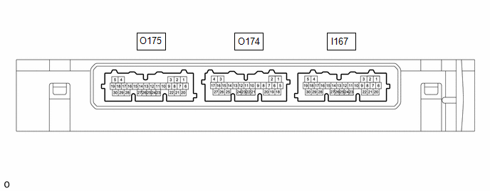
(a) Disconnect the O175 and I167 certification ECU (smart key ECU assembly) connectors.
(b) Measure the resistance and voltage according to the value(s) in the table below.
HINT:
Measure the values on the wire harness side with the connector disconnected.
except Manual Transaxle:
|
Terminal No. (Symbol)
|
Terminal Description
|
Condition
|
Specified Condition
|
Related Data List Item/DTC
|
|
O175-15 (NE) - Body ground
|
Engine speed signal
|
Always
|
10 kΩ or higher
|
|
|
O175-21 (STP1) - Body ground
|
Stop light switch signal
|
Brake pedal depressed → Brake pedal released
|
9 V or higher → 1 V or less
|
|
|
I167-6 (+B) - I167-29 (E)
|
Power source
|
Ignition switch off
|
11 to 14 V
|
-
|
|
I167-14 (P) - I167-29 (E)
|
P position signal
|
Shift position in P → Shift position not in P
|
30 kΩ or higher → Below 200 Ω
|
|
|
O175-22 (CUTB) - Body ground
|
Dark current cut pin*
|
Ignition switch off
|
11 to 14 V
|
-
|
|
I167-29 (E) - Body ground
|
GND
|
Always
|
Below 1 Ω
|
-
|
|
I167-11 (SLP) - I167-29 (E)
|
GND
|
Always
|
Below 1 Ω
|
-
|
|
I167-23 (SSW3) - Body ground
|
SSW3 contact signal
|
Engine switch pushed → Engine switch not pushed
|
Below 15 Ω → 10 kΩ or higher
|
|
|
I167-27 (SSW2) - Body ground
|
SSW2 contact signal
|
Engine switch pushed → Engine switch not pushed
|
Below 15 Ω → 10 kΩ or higher
|
|
|
I167-19 (SSW1) - Body ground
|
SSW1 contact signal
|
Engine switch pushed → Engine switch not pushed
|
Below 15 Ω → 10 kΩ or higher
|
|
-
*: In order to prevent the vehicle auxiliary battery from being depleted when the vehicle is shipped long distances, a fuse that cuts unnecessary electrical load while the vehicle is being shipped is installed in the circuit. If the fuse is removed, the circuit becomes open. If the fuse that is between the vehicle auxiliary battery and terminal CUTB is removed and the circuit is open, the certification ECU (smart key ECU assembly) changes to a certain control mode (example: the transmission of radio waves every 0.25 seconds, which form the detection area, stops).
for Manual Transaxle:
|
Terminal No. (Symbol)
|
Terminal Description
|
Condition
|
Specified Condition
|
Related Data List Item/DTC
|
|
O175-15 (NE) - Body ground
|
Engine speed signal
|
Always
|
10 kΩ or higher
|
|
|
I167-6 (+B) - I167-29 (E)
|
Power source
|
Ignition switch off
|
11 to 14 V
|
-
|
|
O175-22 (CUTB) - Body ground
|
Dark current cut pin*
|
Ignition switch off
|
11 to 14 V
|
-
|
|
I167-29 (E) - Body ground
|
GND
|
Always
|
Below 1 Ω
|
-
|
|
I167-23 (SSW3) - Body ground
|
SSW3 contact signal
|
Engine switch pushed → Engine switch not pushed
|
Below 15 Ω → 10 kΩ or higher
|
|
|
I167-27 (SSW2) - Body ground
|
SSW2 contact signal
|
Engine switch pushed → Engine switch not pushed
|
Below 15 Ω → 10 kΩ or higher
|
|
|
I167-19 (SSW1) - Body ground
|
SSW1 contact signal
|
Engine switch pushed → Engine switch not pushed
|
Below 15 Ω → 10 kΩ or higher
|
|
-
*: In order to prevent the vehicle auxiliary battery from being depleted when the vehicle is shipped long distances, a fuse that cuts unnecessary electrical load while the vehicle is being shipped is installed in the circuit. If the fuse is removed, the circuit becomes open. If the fuse that is between the vehicle auxiliary battery and terminal CUTB is removed and the circuit is open, the certification ECU (smart key ECU assembly) changes to a certain control mode (example: the transmission of radio waves every 0.25 seconds, which form the detection area, stops).
(c) Connect the O175 and I167 certification ECU (smart key ECU assembly) connectors.
(d) Measure the voltage and resistance, and check for pulses according to the value(s) in the table below.
except Manual Transaxle:
|
Terminal No. (Symbol)
|
Terminal Description
|
Condition
|
Specified Condition
|
Related Data List Item/DTC
|
except K121 CVT:
-
O175-3 (STA) - I167-29 (E)
|
When starting the engine, this monitors the voltage sent from terminal STAR to the starter relay to judge whether the engine is "being started".
|
Engine switch pressed and held with brake pedal depressed (starter on) → Approximately 1 second after engine switch released (starter off)
|
6 V or higher*1 → 1.0 V or less
|
-
|
for K121 CVT:
-
O175-3 (STA) - I167-29 (E)
|
P/N position signal
|
Shift lever in P/N → Shift lever not in P/N
|
11 to 14 V → 1.0 V or less
|
-
|
|
O175-10 (STAR) - I167-29 (E)
|
Outputs voltage to the starter relay
-
Outputs voltage (12 V) to the starter relay when starting the engine. (Max. 30 sec. Turns off when an engine speed of 1000 rpm.)
HINT:
When Hi is selected, a start request signal (STAR) will not be output even though a start request signal (STSW) is input.
|
Engine switch pressed and held with brake pedal depressed (starter on) → Approximately 1 second after engine switch released (starter off)
|
6 V or higher*1 → 1.0 V or less
|
-
|
|
O175-15 (NE) - Body ground
|
Engine speed signal
|
Idling (engine warmed up)
|
Pulse generation
(See waveform 1)
|
|
|
I167-8 (LIN) - I167-29 (E)
|
LIN communication line
|
Ignition switch ON
|
Pulse generation
|
-
|
|
I167-14 (P) - I167-29 (E)
|
P position signal
|
Shift position in P → Shift position not in P
|
9 V or higher → 2.76 V or less
|
|
|
I167-23 (SSW3) - I167-29 (E)
|
SSW3 contact signal
|
Engine switch not pushed → Engine switch pushed
|
9 V or higher → 1 V or less
|
|
|
I167-27 (SSW2) - I167-29 (E)
|
SSW2 contact signal
|
Engine switch not pushed → Engine switch pushed
|
9 V or higher → 1 V or less
|
|
|
I167-19 (SSW1) - I167-29 (E)
|
SSW1 contact signal
|
Engine switch not pushed → Engine switch pushed
|
9 V or higher → 1 V or less
|
|
|
I167-21 (ACCD) - I167-29 (E)
|
ACC signal
|
Ignition switch off → Ignition switch ACC
|
1 V or less → 8.5 V or higher
|
|
|
O175-11 (IGRD) - I167-29 (E)
|
IG signal
|
Ignition switch off → Ignition switch ON
|
1 V or less → 9 V or higher
|
Power Source Control
-
IGR Relay Circuit (Outside) Monitor
|
|
O175-24 (IGPD) - I167-29 (E)
|
IG signal
|
Ignition switch off → Ignition switch ON
|
1 V or less → 9 V or higher
|
Power Source Control
-
IGP Relay Circuit (Outside) Monitor
|
|
O175-13 (SPD) - I167-29 (E)
|
Vehicle speed signal
|
Vehicle being driven at approx. 5 km/h (3 mph)
|
Pulse generation
(See waveform 3)
|
Power Source Control
-
Vehicle Running Condition (Line)
|
|
I167-4 (CLG5) - I167-29 (E)
|
Output to No. 1 indoor electrical key antenna assembly (front floor)
|
Procedure:
-
Ignition switch off
-
Electrical key transmitter sub-assembly not inside vehicle
-
Within 30 seconds of closing any door
|
Pulse generation
(See waveform 4)
|
-
|
|
I167-5 (CG5B) - I167-29 (E)
|
Output to No. 1 indoor electrical key antenna assembly (front floor) (terminal on opposite side of component from CLG5 output terminal)
|
Procedure:
-
Ignition switch off
-
Electrical key transmitter sub-assembly not inside vehicle
-
Within 30 seconds of closing any door
|
Pulse generation
(See waveform 4)
|
-
|
|
O174-10 (CLG7) - I167-29 (E)*2
|
for G16E-GTS:
-
Output to No. 2 indoor electrical key antenna assembly (inside luggage compartment)
except G16E-GTS:
-
Output to No. 3 indoor electrical key antenna assembly (inside luggage compartment)
|
Procedure:
-
Ignition switch off
-
Electrical key transmitter sub-assembly not inside vehicle
-
Within 30 seconds of closing any door
|
Pulse generation
(See waveform 4)
|
-
|
|
O174-9 (CG7B) - I167-29 (E)*2
|
for G16E-GTS:
-
Output to No. 2 indoor electrical key antenna assembly (inside luggage compartment) (terminal on opposite side of component from CLG7 output terminal)
except G16E-GTS:
-
Output to No. 3 indoor electrical key antenna assembly (inside luggage compartment) (terminal on opposite side of component from CLG7 output terminal)
|
Procedure:
-
Ignition switch off
-
Electrical key transmitter sub-assembly not inside vehicle
-
Within 30 seconds of closing any door
|
Pulse generation
(See waveform 4)
|
-
|
|
I167-30 (AGND) - Body ground
|
Transponder key amplifier ground
|
Always
|
Below 1 Ω
|
-
|
|
I167-12 (ANT1) - I167-30 (AGND)
|
Signal input / output from transponder key coil (transponder key coil built into engine switch)
|
Ignition switch off, electrical key transmitter sub-assembly not in cabin, within 30 seconds of engine switch pressed
|
Pulse generation
(See waveform 5)
|
|
|
I167-13 (ANT2) - I167-30 (AGND)
|
Signal input / output from transponder key coil (transponder key coil built into engine switch)
|
Ignition switch off, electrical key transmitter sub-assembly not in cabin, within 30 seconds of engine switch pressed
|
Pulse generation
(See waveform 5)
|
|
I167-25 (IND) - I167-29 (E)
|
Security indicator output
|
Ignition switch off → ON
|
Pulse generation → Below 2 V
|
-
|
|
O174-20 (WCSW) - I167-29 (E)*3
|
Wireless charger system stop signal
|
Procedure:
-
Ignition switch off
-
Electrical key transmitter sub-assembly inside vehicle
-
Ignition switch off → ACC or ON
|
Below 1 V → 4.5 to 6 V
(For 1 second after ignition switch to ACC or ON)
|
-
|
-
*1: While the engine is cranking, the auxiliary battery voltage may drop to approximately 6 V.
-
*2: except Sedan
-
*3: w/ Wireless Charger System
for Manual Transaxle:
|
Terminal No. (Symbol)
|
Terminal Description
|
Condition
|
Specified Condition
|
Related Data List Item/DTC
|
|
O175-3 (STA) - I167-29 (E)
|
When starting the engine, this monitors the voltage sent from terminal STAR to the starter relay to judge whether the engine is "being started".
|
Engine switch pressed and held with clutch pedal depressed (starter on) → Approximately 1 second after engine switch released (starter off)
|
6 V or higher*1 → 1.0 V or less
|
-
|
|
O175-10 (STAR) - I167-29 (E)
|
Outputs voltage to the starter relay
-
Outputs voltage (12 V) to the starter relay when starting the engine. (Max. 30 sec. Turns off when an engine speed of 1000 rpm.)
HINT:
When Hi is selected, a start request signal (STAR) will not be output even though a start request signal (STSW) is input.
|
Engine switch pressed and held with clutch pedal depressed (starter on) → Approximately 1 second after engine switch released (starter off)
|
6 V or higher*1 → 1.0 V or less
|
-
|
|
O175-15 (NE) - Body ground
|
Engine speed signal
|
Idling (engine warmed up)
|
Pulse generation
(See waveform 1)
|
|
|
I167-11 (SLP) - I167-29 (E)
|
Steering lock position signal
|
Steering locked → Steering unlocked
|
11 to 14 V → 1.5 V or less
|
|
|
I167-24 (SLR+) - I167-29 (E)
|
Steering lock motor operation command signal
(Steering lock motor operation permission signal sent from the certification ECU (smart key ECU assembly))
|
When a door is opened, the steering lock motor will be operated if all of the following conditions are met:
-
The steering is unlocked.
-
The ignition switch is off.
-
The shift position is in P.
|
Pulse generation
(See waveform 2)
|
-
|
|
I167-8 (LIN) - I167-29 (E)
|
LIN communication line
|
Ignition switch ON
|
Pulse generation
|
Smart Key
-
Steering Lock Start Condition
|
|
I167-23 (SSW3) - I167-29 (E)
|
SSW3 contact signal
|
Engine switch not pushed → Engine switch pushed
|
9 V or higher → 1 V or less
|
|
|
I167-27 (SSW2) - I167-29 (E)
|
SSW2 contact signal
|
Engine switch not pushed → Engine switch pushed
|
9 V or higher → 1 V or less
|
|
|
I167-19 (SSW1) - I167-29 (E)
|
SSW1 contact signal
|
Engine switch not pushed → Engine switch pushed
|
9 V or higher → 1 V or less
|
|
|
I167-21 (ACCD) - I167-29 (E)
|
ACC signal
|
Ignition switch off → Ignition switch ACC
|
1 V or less → 8.5 V or higher
|
|
|
O175-11 (IGRD) - I167-29 (E)
|
IG signal
|
Ignition switch off → Ignition switch ON
|
1 V or less → 9 V or higher
|
Power Source Control
-
IGR Relay Circuit (Outside) Monitor
|
|
O175-24 (IGPD) - I167-29 (E)
|
IG signal
|
Ignition switch off → Ignition switch ON
|
1 V or less → 9 V or higher
|
Power Source Control
-
IGP Relay Circuit (Outside) Monitor
|
|
O175-13 (SPD) - I167-29 (E)
|
Vehicle speed signal
|
Vehicle being driven at approx. 5 km/h (3 mph)
|
Pulse generation
(See waveform 3)
|
Power Source Control
-
Vehicle Running Condition (Line)
|
|
I167-4 (CLG5) - I167-29 (E)
|
Output to No. 1 indoor electrical key antenna assembly (front floor)
|
Procedure:
-
Ignition switch off
-
Electrical key transmitter sub-assembly not inside vehicle
-
Within 30 seconds of closing any door
|
Pulse generation
(See waveform 4)
|
-
|
|
I167-5 (CG5B) - I167-29 (E)
|
Output to No. 1 indoor electrical key antenna assembly (front floor) (terminal on opposite side of component from CLG5 output terminal)
|
Procedure:
-
Ignition switch off
-
Electrical key transmitter sub-assembly not inside vehicle
-
Within 30 seconds of closing any door
|
Pulse generation
(See waveform 4)
|
-
|
|
O174-10 (CLG7) - I167-29 (E)*2
|
for G16E-GTS:
-
Output to No. 2 indoor electrical key antenna assembly (inside luggage compartment)
except G16E-GTS:
-
Output to No. 3 indoor electrical key antenna assembly (inside luggage compartment)
|
Procedure:
-
Ignition switch off
-
Electrical key transmitter sub-assembly not inside vehicle
-
Within 30 seconds of closing any door
|
Pulse generation
(See waveform 4)
|
-
|
|
O174-9 (CG7B) - I167-29 (E)*2
|
for G16E-GTS:
-
Output to No. 2 indoor electrical key antenna assembly (inside luggage compartment) (terminal on opposite side of component from CLG7 output terminal)
except G16E-GTS:
-
Output to No. 3 indoor electrical key antenna assembly (inside luggage compartment) (terminal on opposite side of component from CLG7 output terminal)
|
Procedure:
-
Ignition switch off
-
Electrical key transmitter sub-assembly not inside vehicle
-
Within 30 seconds of closing any door
|
Pulse generation
(See waveform 4)
|
-
|
|
I167-30 (AGND) - Body ground
|
Transponder key amplifier ground
|
Always
|
Below 1 Ω
|
-
|
|
I167-12 (ANT1) - I167-30 (AGND)
|
Signal input / output from transponder key coil (transponder key coil built into engine switch)
|
Ignition switch off, electrical key transmitter sub-assembly not in cabin, within 30 seconds of engine switch pressed
|
Pulse generation
(See waveform 5)
|
|
|
I167-13 (ANT2) - I167-30 (AGND)
|
Signal input / output from transponder key coil (transponder key coil built into engine switch)
|
Ignition switch off, electrical key transmitter sub-assembly not in cabin, within 30 seconds of engine switch pressed
|
Pulse generation
(See waveform 5)
|
|
I167-25 (IND) - I167-29 (E)
|
Security indicator output
|
Ignition switch off → ON
|
Pulse generation → Below 2 V
|
-
|
|
O174-20 (WCSW) - I167-29 (E)*3
|
Wireless charger system stop signal
|
Procedure:
-
Ignition switch off
-
Electrical key transmitter sub-assembly inside vehicle
-
Ignition switch off → ACC or ON
|
Below 1 V → 4.5 to 6 V
(For 1 second after ignition switch to ACC or ON)
|
-
|
-
*1: While the engine is cranking, the auxiliary battery voltage may drop to approximately 6 V.
-
*2: except Sedan
-
*3: w/ Wireless Charger System
HINT:
-
The waveform of the steering lock actuator motor stopped can be checked without performing any particular operation.
-
The waveform of the steering lock actuator motor operating can be checked if either of the following operations is performed:
-
To unlock the steering, bring the electrical key transmitter sub-assembly into the cabin and turn the ignition switch to ACC or ON.
-
To lock the steering, open a door with the ignition switch off.
(e) Using an oscilloscope, check the waveform of the ECU.
NOTICE:
The oscilloscope waveform shown in the illustration is an example for reference only. Noise, chattering, etc. are not shown.
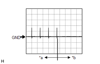
(1) Waveform 1
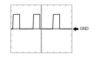
Measurement Condition
|
Item
|
Content
|
|
Tester Connection
|
O175-15 (NE) - Body ground
|
|
Tool Setting
|
5 V/DIV., 2 ms./DIV.
|
|
Condition
|
Idling (engine warmed up)
|
HINT:
The wavelength becomes shorter as the engine speed increases.
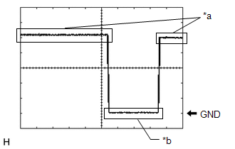
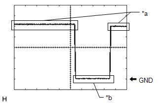
(2) Waveform 2 (for Manual Transaxle)
|
*a
|
Steering lock motor not operating
|
|
*b
|
Steering lock motor operating
|
Measurement Condition
|
Item
|
Content
|
|
Tester Connection
|
I167-24 (SLR+) - I167-29 (E)
|
|
Tool Setting
|
2 V/DIV., 200 ms./DIV.
|
|
Condition
|
When a door is opened, the steering lock motor will be operated if all of the following conditions are met:
-
The steering is unlocked.
-
The ignition switch is off.
|
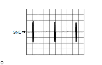
(3) Waveform 3
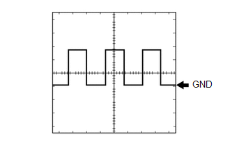
Measurement Condition
|
Item
|
Content
|
|
Tester Connection
|
O175-13 (SPD) - I167-29 (E)
|
|
Tool Setting
|
5 V/DIV., 20 ms./DIV.
|
|
Condition
|
Vehicle being driven at approx. 5 km/h (3 mph)
|
HINT:
The wavelength becomes shorter as the vehicle speed increases.
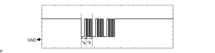
(4) Waveform 4
|
*a
|
For 30 seconds after any door closed
|
|
*b
|
After 30 seconds or more have elapsed since any door closed
|
Measurement Condition
|
Item
|
Content
|
|
Tester Connection
|
I167-4 (CLG5) - I167-29 (E)
I167-5 (CG5B) - I167-29 (E)
O174-10 (CLG7) - I167-29 (E)*
O174-9 (CG7B) - I167-29 (E)*
|
|
Tool Setting
|
5 V/DIV., 500 ms./DIV.
|
|
Condition
|
Procedure:
-
Ignition switch off
-
Electrical key transmitter sub-assembly not inside vehicle
-
Within 30 seconds of closing any door
|
(5) Waveform 5
Measurement Condition
|
Item
|
Content
|
|
Tester Connection
|
I167-12 (ANT1) - I167-30 (AGND)
I167-13 (ANT2) - I167-30 (AGND)
|
|
Tool Setting
|
5 V/DIV.,200 ms/DIV.
|
|
Condition
|
Ignition switch off, electrical key transmitter sub-assembly not in cabin, within 30 seconds of engine switch pressed
|
CHECK STEERING LOCK ECU (STEERING LOCK ACTUATOR OR UPPER BRACKET ASSEMBLY) (for Manual Transaxle)

(a) Disconnect the I59 steering lock ECU (steering lock actuator or upper bracket assembly) connector.
(b) Measure the voltage and resistance according to the value(s) in the table below.
HINT:
Measure the values on the wire harness side with the connector disconnected.
|
Terminal No. (Symbol)
|
Terminal Description
|
Condition
|
Specified Condition
|
Related Data List Item/DTC
|
|
I59-1 (GND) - Body ground
|
Ground
|
Always
|
Below 1 Ω
|
-
|
|
I59-7 (B) - Body ground
|
Constant power supply
|
Ignition switch off
|
11 to 14 V
|
-
|
(c) Connect the I59 steering lock ECU (steering lock actuator or upper bracket assembly) connector.
(d) Measure the voltage, and check for pulses according to the value(s) in the table below.
|
Terminal No. (Symbol)
|
Terminal Description
|
Condition
|
Specified Condition
|
Related Data List Item/DTC
|
|
I59-3 (IGE) - I59-1 (GND)
|
Steering lock motor operation permission signal (motor operation permission signal supplied by certification ECU (smart key ECU assembly))
|
Steering lock motor operating when all conditions met, and then door opened:
-
Steering unlocked
-
Ignition switch turned off
|
Pulse generation
(See waveform 1)
|
Smart Key
-
Power Supply Short History
-
Unlock Request Receive
-
Steering Lock Request Receive
|
|
I59-4 (SLP1) - I59-1 (GND)
|
Steering lock bar position signal (signal output from steering unlock sensor)
|
Steering locked → unlocked
|
11 to 14 V → Below 1.5 V
|
Smart Key
-
Sensor Malfunction History
|
|
I59-5 (LIN) - I59-1 (GND)
|
LIN communication line
|
Ignition switch ON
|
Pulse generation
|
Smart Key
-
Steering Lock Start Condition
|
|
I59-6 (SLA) - I59-1 (GND)
|
Steering lock motor operation permission signal (motor operation permission signal supplied by certification ECU (smart key ECU assembly))
|
Ignition switch off → ON
|
Below 1 V → 11 to 14 V
|
-
|
HINT:
-
There is 1 motor and 2 sensors built into the steering lock actuator or upper bracket assembly.
-
When taking measurements when the lock motor is stopped, it is not necessary to perform any operations.
-
In order to take measurements when the lock motor is operating, perform either of the following operations:
-
To unlock the steering, carry the key and turn the ignition switch to ACC or ON.
-
To lock the steering, turn the ignition switch off, and then open a door.
(e) Using an oscilloscope, check the waveform of the ECU.
NOTICE:
The oscilloscope waveform shown in the illustration is an example for reference only. Noise, chattering, etc. are not shown.
Waveform 1
|
*a
|
Steering lock motor not operating
|
|
*b
|
Steering lock motor operating
|
Measurement Condition
|
Item
|
Content
|
|
Tester Connection
|
I59-3 (IGE) - I59-1 (GND)
|
|
Tool Setting
|
2 V/DIV., 200 ms./DIV.
|
|
Condition
|
Steering lock motor operating when all conditions met, and then door opened:
-
Steering unlocked
-
Ignition switch turned off
|
CHECK ID CODE BOX (IMMOBILISER CODE ECU)

(a) Disconnect the I20 ID code box (immobiliser code ECU) connector.
(b) Measure the voltage and resistance according to the value(s) in the table below.
HINT:
Measure the values on the wire harness side with the connector disconnected.
|
Terminal No. (Symbol)
|
Terminal Description
|
Condition
|
Specified Condition
|
Related Data List Item
|
|
I20-1 (+B) - Body ground
|
Power source
|
Ignition switch off
|
11 to 14 V
|
-
|
|
I20-5 (GND) - Body ground
|
Ground
|
Always
|
Below 1 Ω
|
(c) Reconnect the I20 ID code box (immobiliser code ECU) connector.
(d) Measure the voltage and check for pulses according to the value(s) in the table below.
|
Terminal No. (Symbol)
|
Terminal Description
|
Condition
|
Specified Condition
|
Related Data List Item
|
|
I20-3 (EFII) - I20-5 (GND)
|
EFI communication input
(Signal input from ECM to ID code box (immobiliser code ECU))
|
Ignition switch off
|
11 to 14 V
|
Smart Key
-
EFI Code Receive
-
Start Request
|
|
I20-3 (EFII) - I20-5 (GND)
|
EFI communication input
(Signal input from ECM to ID code box (immobiliser code ECU))
|
Within 3 seconds of engine start or within 3 seconds of ignition switch turned to ON after cable disconnected and reconnected to auxiliary battery
|
Pulse generation
(See waveform 1)
|
|
I20-4 (EFIO) - I20-5 (GND)
|
EFI communication output
(Signal output from ID code box (immobiliser code ECU) to ECM)
|
Ignition switch off
|
Below 1 V
|
|
I20-4 (EFIO) - I20-5 (GND)
|
EFI communication output
(Signal output from ID code box (immobiliser code ECU) to ECM)
|
Within 3 seconds of engine start or within 3 seconds of ignition switch turned to ON after cable disconnected and reconnected to auxiliary battery
|
Pulse generation
(See waveform 2)
|
|
I20-2 (LIN1) - I20-5 (GND)
|
LIN communication line
|
Ignition switch ON
|
Pulse generation
|
Smart Key
-
Steering Lock Start Cond*
|
(e) Using an oscilloscope, check the waveform.
NOTICE:
The waveform shown in the illustration is an example for reference only. Noise, chattering, etc. are not shown.
(1) Waveform 1
|
*a
|
Approximately 160 ms.
|
*b
|
Approximately 270 ms.
|
|
Item
|
Content
|
|
Tester Connection
|
I20-3 (EFII) - I20-5 (GND)
|
|
Tool Setting
|
2 V/DIV., 500 ms./DIV.
|
|
Condition
|
Within 3 seconds of engine start or within 3 seconds of ignition switch turned to ON after cable disconnected and reconnected to auxiliary battery
|
(2) Waveform 2
|
*a
|
Approximately 160 ms.
|
*b
|
Approximately 270 ms.
|
|
Item
|
Content
|
|
Tester Connection
|
I20-4 (EFIO) - I20-5 (GND)
|
|
Tool Setting
|
2 V/DIV., 500 ms./DIV.
|
|
Condition
|
Within 3 seconds of engine start or within 3 seconds of ignition switch turned to ON after cable disconnected and reconnected to auxiliary battery
|
CHECK ECM (for M20A-FKS (except K121 CVT))
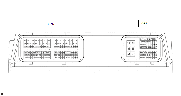
(a) Measure the voltage and resistance, and check for pulses according to the value(s) in the table below.
|
Terminal No. (Symbol)
|
Terminal Description
|
Condition
|
Specified Condition
|
Related Data List Item/DTC
|
|
A47-1 (BATT) - A47-10 (E1)
|
+B power supply
|
Always
|
11 to 14 V
|
-
|
|
A47-9 (+B) - A47-10 (E1)
|
+B power supply
|
Always
|
11 to 14 V
|
-
|
|
A47-35 (+B2) - A47-10 (E1)
|
+B power supply
|
Always
|
11 to 14 V
|
-
|
|
A47-10 (E1) - Body ground
|
Ground
|
Always
|
Below 1 Ω
|
-
|
|
A47-25 (IMO) - A47-10 (E1)
|
EFI communication input (Signal input from ECM to ID code box (immobiliser code ECU))
|
Ignition switch off
|
11 to 14 V
|
Smart Key
-
EFI Code Receive
-
Engine Start Request
|
|
A47-25 (IMO) - A47-10 (E1)
|
EFI communication input (Signal input from ECM to ID code box (immobiliser code ECU))
|
Within 3 seconds of engine start or within 3 seconds of ignition switch turned to ON after cable disconnected and reconnected to auxiliary battery
|
Pulse generation
(See waveform 1)
|
|
A47-26 (IMI) - A47-10 (E1)
|
EFI communication input (Signal output from ID code box (immobiliser code ECU) to ECM)
|
Ignition switch off
|
1 V or less
|
|
A47-26 (IMI) - A47-10 (E1)
|
EFI communication input (Signal output from ID code box (immobiliser code ECU) to ECM)
|
Within 3 seconds of engine start or within 3 seconds of ignition switch turned to ON after cable disconnected and reconnected to auxiliary battery
|
Pulse generation (See waveform 2)
|
|
A47-16 (NEO) - A47-10 (E1)
|
Engine speed signal
|
Idling (engine warmed up)
|
Pulse generation (See waveform 3)
|
|
|
A47-30 (STA) - A47-10 (E1)
|
When starting the engine, this monitors the voltage sent from terminal STAR to the starter relay to judge whether the engine is "being started".
|
Engine is cranking
|
6 V or higher
|
-
|
(b) Using an oscilloscope, check the waveform.
NOTICE:
The waveform shown in the illustration is an example for reference only. Noise, chattering, etc. are not shown.
(1) Waveform 1 (Reference)
|
*a
|
Approximately 160 ms.
|
*b
|
Approximately 270 ms.
|
Measurement Condition
|
Item
|
Content
|
|
Tester Connection
|
A47-25 (IMO) - A47-10 (E1)
|
|
Tool Setting
|
2 V/DIV., 500 ms./DIV.
|
|
Condition
|
Within 3 seconds of engine start or within 3 seconds of ignition switch turned to ON after cable disconnected and reconnected to auxiliary battery
|
(2) Waveform 2 (Reference)
|
*a
|
Approximately 160 ms.
|
*b
|
Approximately 270 ms.
|
Measurement Condition
|
Item
|
Content
|
|
Tester Connection
|
A47-26 (IMI) - A47-10 (E1)
|
|
Tool Setting
|
2 V/DIV., 500 ms./DIV.
|
|
Condition
|
Within 3 seconds of engine start or within 3 seconds of ignition switch turned to ON after cable disconnected and reconnected to auxiliary battery
|
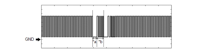
(3) Waveform 3
Measurement Condition
|
Item
|
Content
|
|
Tester Connection
|
A47-16 (NEO) - A47-10 (E1)
|
|
Tool Setting
|
5 V/DI., 2 ms./DIV.
|
|
Condition
|
Idling (engine warmed up)
|
HINT:
The wavelength becomes shorter as the engine speed increases.
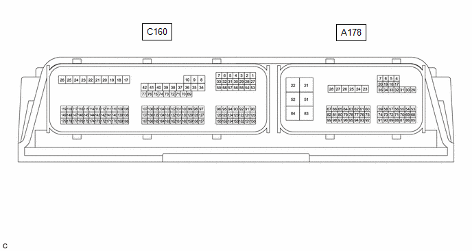
CHECK ECM (for M20A-FKS (K121 CVT))
(a) Measure the voltage and resistance, and check for pulses according to the value(s) in the table below.
|
Terminal No. (Symbol)
|
Terminal Description
|
Condition
|
Specified Condition
|
Related Data List Item/DTC
|
|
A178-31 (BATT) - A178-22 (E1)
|
+B power supply
|
Always
|
11 to 14 V
|
-
|
|
A178-22 (E1) - Body ground
|
Ground
|
Always
|
Below 1 Ω
|
-
|
|
A178-55 (IMO) - A178-22 (E1)
|
EFI communication input
(Signal input from ECM to ID code box (immobiliser code ECU))
|
Ignition switch off
|
11 to 14 V
|
Entry&Start
-
EFI Code Receive
-
Engine Start Request
|
|
A178-55 (IMO) - A178-22 (E1)
|
EFI communication input
(Signal input from ECM to ID code box (immobiliser code ECU))
|
Within 3 seconds of engine start or within 3 seconds of ignition switch turned to ON after cable disconnected and reconnected to auxiliary battery
|
Pulse generation
(See waveform 1)
|
|
A178-54 (IMI) - A178-22 (E1)
|
EFI communication input
(Signal output from ID code box (immobiliser code ECU) to ECM)
|
Ignition switch off
|
1 V or less
|
|
A178-54 (IMI) - A178-22 (E1)
|
EFI communication input
(Signal output from ID code box (immobiliser code ECU) to ECM)
|
Ignition switch turned to ON using registered electrical key transmitter sub-assembly
|
Pulse generation
(See waveform 2)
|
|
A178-66 (NEO) - A178-22 (E1)
|
Engine speed signal
|
Idling (engine warmed up)
|
Pulse generation
(See waveform 3)
|
|
|
A178-18 (STA) - A178-22 (E1)
|
When starting the engine, this monitors the voltage sent from terminal STAR to the starter relay to judge whether the engine is "being started".
|
Engine is cranking
|
6 V or higher
|
-
|
|
A178-81 (PPOS) - A178-22 (E1)
|
P/N position signal
|
Engine switch pressed and held with brake pedal depressed (starter on) → Approximately 1 second after engine switch released (starter off)
|
9.45 V or higher → 1.0 V or less
|
-
|
(b) Using an oscilloscope, check the waveform.
NOTICE:
The waveform shown in the illustration is an example for reference only. Noise, chattering, etc. are not shown.
(1) Waveform 1 (Reference)
|
*a
|
Approximately 160 ms.
|
*b
|
Approximately 270 ms.
|
Measurement Condition
|
Item
|
Content
|
|
Tester Connection
|
A178-55 (IMO) - A178-22 (E1)
|
|
Tool Setting
|
2 V/DIV., 500 ms./DIV.
|
|
Condition
|
Within 3 seconds of engine start or within 3 seconds of ignition switch turned to ON after cable disconnected and reconnected to auxiliary battery
|
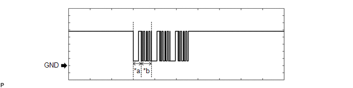
(2) Waveform 2 (Reference)
|
*a
|
Approximately 160 ms.
|
*b
|
Approximately 270 ms.
|
Measurement Condition
|
Item
|
Content
|
|
Tester Connection
|
A178-54 (IMI) - A178-22 (E1)
|
|
Tool Setting
|
2 V/DIV., 500 ms./DIV.
|
|
Condition
|
Ignition switch turned to ON using registered electrical key transmitter sub-assembly
|
(3) Waveform 3
Measurement Condition
|
Item
|
Content
|
|
Tester Connection
|
A178-66 (NEO) - A178-22 (E1)
|
|
Tool Setting
|
2 V/DI., 2 ms./DIV.
|
|
Condition
|
Idling (engine warmed up)
|
HINT:
The wavelength becomes shorter as the engine speed increases.
CHECK ECM (for G16E-GTS)
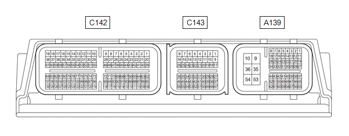
(a) Measure the voltage and resistance, and check for pulses according to the value(s) in the table below.
|
Terminal No. (Symbol)
|
Terminal Description
|
Condition
|
Specified Condition
|
Related Data List Item/DTC
|
|
A139-1 (BATT) - A139-10 (E1)
|
+B power supply
|
Always
|
11 to 14 V
|
-
|
|
A139-9 (+B) - A139-10 (E1)
|
+B power supply
|
Always
|
11 to 14 V
|
-
|
|
A139-35 (+B2) - A139-10 (E1)
|
+B power supply
|
Always
|
11 to 14 V
|
-
|
|
A139-10 (E1) - Body ground
|
Ground
|
Always
|
Below 1 Ω
|
-
|
|
A139-47 (IMO) - A139-10 (E1)
|
EFI communication input (Signal input from ECM to ID code box (immobiliser code ECU))
|
Ignition switch off
|
11 to 14 V
|
Smart Key
-
EFI Code Receive
-
Engine Start Request
|
|
A139-47 (IMO) - A139-10 (E1)
|
EFI communication input (Signal input from ECM to ID code box (immobiliser code ECU))
|
Within 3 seconds of engine start or within 3 seconds of ignition switch turned to ON after cable disconnected and reconnected to auxiliary battery
|
Pulse generation
(See waveform 1)
|
|
A139-61 (IMI) - A139-10 (E1)
|
EFI communication input (Signal output from ID code box (immobiliser code ECU) to ECM)
|
Ignition switch off
|
1 V or less
|
|
A139-61 (IMI) - A139-10 (E1)
|
EFI communication input (Signal output from ID code box (immobiliser code ECU) to ECM)
|
Within 3 seconds of engine start or within 3 seconds of ignition switch turned to ON after cable disconnected and reconnected to auxiliary battery
|
Pulse generation (See waveform 2)
|
|
A139-16 (NEO) - A139-10 (E1)
|
Engine speed signal
|
Idling (engine warmed up)
|
Pulse generation (See waveform 3)
|
|
|
A139-30 (STA) - A139-10 (E1)
|
When starting the engine, this monitors the voltage sent from terminal STAR to the starter relay to judge whether the engine is "being started".
|
Engine is cranking
|
6 V or higher
|
-
|
(b) Using an oscilloscope, check the waveform.
NOTICE:
The waveform shown in the illustration is an example for reference only. Noise, chattering, etc. are not shown.
(1) Waveform 1 (Reference)
|
*a
|
Approximately 160 ms.
|
*b
|
Approximately 270 ms.
|
Measurement Condition
|
Item
|
Content
|
|
Tester Connection
|
A139-47 (IMO) - A139-10 (E1)
|
|
Tool Setting
|
2 V/DIV., 500 ms./DIV.
|
|
Condition
|
Within 3 seconds of engine start or within 3 seconds of ignition switch turned to ON after cable disconnected and reconnected to auxiliary battery
|
(2) Waveform 2 (Reference)
|
*a
|
Approximately 160 ms.
|
*b
|
Approximately 270 ms.
|
Measurement Condition
|
Item
|
Content
|
|
Tester Connection
|
A139-61 (IMI) - A139-10 (E1)
|
|
Tool Setting
|
2 V/DIV., 500 ms./DIV.
|
|
Condition
|
Within 3 seconds of engine start or within 3 seconds of ignition switch turned to ON after cable disconnected and reconnected to auxiliary battery
|
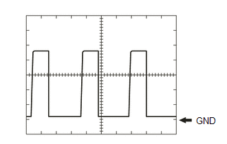
(3) Waveform 3

Measurement Condition
|
Item
|
Content
|
|
Tester Connection
|
A139-16 (NEO) - A139-10 (E1)
|
|
Tool Setting
|
5 V/DI., 2 ms./DIV.
|
|
Condition
|
Idling (engine warmed up)
|
HINT:
The wavelength becomes shorter as the engine speed increases.
CHECK ENGINE SWITCH

(a) Disconnect the I35 engine switch connector.
(b) Measure the resistance according to the value(s) in the table below.
|
Terminal No. (Symbol)
|
Terminal Description
|
Condition
|
Specified Condition
|
Related Data List Item/DTC
|
|
I35-3 (GND) - Body ground
|
Transponder key amplifier ground
|
Always
|
Below 1 Ω
|
-
|
(c) Connect the I35 engine switch connector.
(d) Measure the voltage and check for pulses according to the value(s) in the table below.
|
Terminal No. (Symbol)
|
Terminal Description
|
Condition
|
Specified Condition
|
Related Data List Item/DTC
|
|
I35-1 (ANT1) - I35-3 (GND)
|
Signal input / output from transponder key coil (transponder key coil built into engine switch)
|
Ignition switch off, electrical key transmitter sub-assembly not in cabin, within 30 seconds of engine switch pressed
|
Pulse generation
(See waveform 1)
|
|
|
I35-7 (ANT2) - I35-3 (GND)
|
Signal input / output from transponder key coil (transponder key coil built into engine switch)
|
Ignition switch off, electrical key transmitter sub-assembly not in cabin, within 30 seconds of engine switch pressed
|
Pulse generation
(See waveform 1)
|
|
I35-11 (SS3) - I35-3 (GND)
|
SS3 contact signal
HINT:
Backup for SS1. Behaves the same way as SS1.
|
Engine switch not pushed → Engine switch pushed
|
9 V or higher → Below 1 V
|
|
|
I35-6 (SS2) - I35-3 (GND)
|
SS2 contact signal
HINT:
Backup for SS1. Behaves the same way as SS1.
|
Engine switch not pushed → Engine switch pushed
|
9 V or higher → Below 1 V
|
|
|
I35-12 (SS1) - I35-3 (GND)
|
SS1 contact signal
|
Engine switch not pushed → Engine switch pushed
|
9 V or higher → Below 1 V
|
|
(e) Using an oscilloscope, check the waveform.
NOTICE:
The waveform shown in the illustration is an example for reference only. Noise, chattering, etc. are not shown.
(1) Waveform 1 (Reference)
Measurement Condition
|
Item
|
Content
|
|
Tester Connection
|
I35-1 (ANT1) - I35-3 (GND)
I35-7 (ANT2) - I35-3 (GND)
|
|
Tool Setting
|
5 V/DIV.,200 ms/DIV.
|
|
Condition
|
Ignition switch off, electrical key transmitter sub-assembly not in cabin, within 30 seconds of engine switch pressed
|
SMART KEY SYSTEM (for Entry Function)
Click here
![2023 - 2025 MY Corolla Corolla Hatchback Corolla HV GR Corolla [11/2022 - ]; THEFT DETERRENT / KEYLESS ENTRY: SMART KEY SYSTEM (for Entry Function): TERMINALS OF ECU](/t3Portal/stylegraphics/info.gif)
|