- DTC judgment completed
- System normal
| Last Modified: 08-23-2025 | 6.11:8.1.0 | Doc ID: RM100000002B365 |
| Model Year Start: 2023 | Model: Corolla Hatchback | Prod Date Range: [03/2023 - ] |
| Title: K120 / K121 (CVT): K121 CONTINUOUSLY VARIABLE TRANSAXLE SYSTEM: P17029F; AT Solenoids Operation Shutdown Circuit Stuck Off; 2023 - 2026 MY Corolla Corolla Hatchback [03/2023 - ] | ||
|
DTC |
P17029F |
AT Solenoids Operation Shutdown Circuit Stuck Off |
DESCRIPTION
The ECM detects a malfunction in the current cut circuit used to transition to a fail-safe gear position.
|
DTC No. |
Detection Item |
DTC Detection Condition |
Trouble Area |
MIL |
DTC Output from |
Priority |
Note |
|---|---|---|---|---|---|---|---|
|
P17029F |
AT Solenoids Operation Shutdown Circuit Stuck Off |
Any of the following conditions is detected for 0.1 seconds or more during a solenoid current cut request with the ignition switch off (1-trip detection logic):
|
|
Does not come on |
Engine |
B |
SAE Code: P1702 |
MONITOR DESCRIPTION
When the ignition switch is off and current is detected as flowing to the solenoid valve during a solenoid current cut request, the ECM stores a DTC.
CONFIRMATION DRIVING PATTERN
HINT:
After repairs have been completed, clear the DTCs and then check that the vehicle has returned to normal by performing the following All Readiness check procedure.
- Clear the DTCs (even if no DTCs are stored, perform the clear DTC procedure).
- Turn the ignition switch off and wait for 2 minutes or more.
- Turn the ignition switch to ON.
- Enter the following menus: Powertrain / Engine / Utility / All Readiness.
- Input the DTC: P17029F.
-
Check the DTC judgment result.
GTS Display
Description
NORMAL
ABNORMAL
- DTC judgment completed
- System abnormal
INCOMPLETE
- DTC judgment not completed
- Perform driving pattern after confirming DTC enabling conditions
N/A
- Unable to perform DTC judgment
- Number of DTCs which do not fulfill DTC preconditions has reached ECU memory limit
HINT:
- If the judgment result shows NORMAL, the system is normal.
- If the judgment result shows ABNORMAL, the system has a malfunction.
- If the judgment result shows INCOMPLETE or N/A, perform the Confirmation Driving Pattern and check the DTC judgment result again.
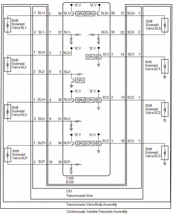
WIRING DIAGRAM
CAUTION / NOTICE / HINT
NOTICE:
-
Perform registration and/or initialization when parts related to the continuously variable transaxle system are replaced.
Click here
![2023 - 2026 MY Corolla Corolla Hatchback [03/2023 - ]; K120 / K121 (CVT): K121 CONTINUOUSLY VARIABLE TRANSAXLE SYSTEM: PRECAUTION](/t3Portal/stylegraphics/info.gif)
-
Check that no DTCs are stored after performing initialization.
Click here
HINT:
If any DTCs other than DTC P17029F are output, perform troubleshooting for those DTCs first.
PROCEDURE
|
1. |
CHECK DTC OUTPUT (IN ADDITION TO DTC P17029F) |
(a) Read the DTCs using the GTS.
Powertrain > Engine > Trouble Codes
|
Result |
Proceed to |
|---|---|
|
Only P17029F is output |
A |
|
P17029F and other DTCs are output |
B |
| B |

|
GO TO DTC CHART |
|

|
2. |
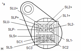
INSPECT TRANSMISSION WIRE (SHIFT SOLENOID VALVE SL1, SL2, SLU, SLP, SLS, SC1, SC2 and SC3) |
Pre-procedure1
(a) Disconnect the C61 transmission wire connector.
Procedure1
|
(b) Measure the resistance according to the value(s) in the table below. Standard Resistance:
Result:
|
|
Post-procedure1
(c) Connect the C61 transmission wire connector.
| NG |
|
|
|
3. |
CHECK HARNESS AND CONNECTOR (TRANSMISSION WIRE - ECM) |
Pre-procedure1
(a) Disconnect the C160 ECM connector.
(b) Disconnect the C61 transmission wire connector.
Procedure1
(c) Measure the resistance according to the value(s) in the table below.
Standard Resistance:
|
Tester Connection |
Condition |
Specified Condition |
|---|---|---|
|
C61-2 (SL1+) - C160-56 (SL1+) |
Always |
Below 1 Ω |
|
C61-7 (SL1-) - C160-57 (SL1-) |
Always |
Below 1 Ω |
|
C61-3 (SL2+) - C160-7 (SL2+) |
Always |
Below 1 Ω |
|
C61-8 (SL2-) - C160-6 (SL2-) |
Always |
Below 1 Ω |
|
C61-4 (SLU+) - C160-30 (SLU+) |
Always |
Below 1 Ω |
|
C61-9 (SLU-) - C160-31 (SLU-) |
Always |
Below 1 Ω |
|
C61-5 (SLP+) - C160-54 (SLP+) |
Always |
Below 1 Ω |
|
C61-10 (SLP-) - C160-55 (SLP-) |
Always |
Below 1 Ω |
|
C61-15 (SLS+) - C160-58 (SLS+) |
Always |
Below 1 Ω |
|
C61-20 (SLS-) - C160-59 (SLS-) |
Always |
Below 1 Ω |
|
C61-14 (SC1) - C160-3 (SC1) |
Always |
Below 1 Ω |
|
C61-13 (SC2) - C160-2 (SC2) |
Always |
Below 1 Ω |
|
C61-18 (SC3) - C160-1 (SC3) |
Always |
Below 1 Ω |
|
C61-2 (SL1+) or C160-56 (SL1+) - Body ground and other terminals |
Always |
10 kΩ or higher |
|
C61-7 (SL1-) or C160-57 (SL1-)- Body ground and other terminals |
Always |
10 kΩ or higher |
|
C61-3 (SL2+) or C160-7 (SL2+) - Body ground and other terminals |
Always |
10 kΩ or higher |
|
C61-8 (SL2-) or C160-6 (SL2-)- Body ground and other terminals |
Always |
10 kΩ or higher |
|
C61-4 (SLU+) or C160-30 (SLU+) - Body ground and other terminals |
Always |
10 kΩ or higher |
|
C61-9 (SLU-) or C160-31 (SLU-)- Body ground and other terminals |
Always |
10 kΩ or higher |
|
C61-5 (SLP+) or C160-54 (SLP+) - Body ground and other terminals |
Always |
10 kΩ or higher |
|
C61-10 (SLP-) or C160-55 (SLP-)- Body ground and other terminals |
Always |
10 kΩ or higher |
|
C61-15 (SLS+) or C160-58 (SLS+) - Body ground and other terminals |
Always |
10 kΩ or higher |
|
C61-20 (SLS-) or C160-59 (SLS-)- Body ground and other terminals |
Always |
10 kΩ or higher |
|
C61-14 (SC1) or C160-3 (SC1)- Body ground and other terminals |
Always |
10 kΩ or higher |
|
C61-13 (SC2) or C160-2 (SC2)- Body ground and other terminals |
Always |
10 kΩ or higher |
|
C61-18 (SC3) or C160-1 (SC3)- Body ground and other terminals |
Always |
10 kΩ or higher |
Post-procedure1
(d) Connect the C160 ECM connector.
(e) Connect the C61 transmission wire connector.
| NG |
|
REPAIR OR REPLACE HARNESS OR CONNECTOR (TRANSMISSION WIRE - ECM) |
|
|
4. |
REPLACE ECM |
HINT:
Click here
| NEXT |
|
PERFORM REGISTRATION AND INITIALIZATION for Registration: Click here
for Initialization: Click here
|
|
5. |
INSPECT TRANSMISSION VALVE BODY ASSEMBLY (SHIFT SOLENOID VALVE SL1, SL2, SLU, SLP, SLS, SC1, SC2 and SC3) |
Click here
| OK |
|
REPLACE TRANSMISSION WIRE
|
|
|
6. |
REPLACE TRANSMISSION VALVE BODY ASSEMBLY |
HINT:
Click here
| NEXT |
|
PERFORM REGISTRATION AND INITIALIZATION for Registration: Click here
for Initialization: Click here
|
|
|
|