| Last Modified: 05-13-2024 | 6.11:8.1.0 | Doc ID: RM10000000297ED |
| Model Year Start: 2023 | Model: GR Corolla | Prod Date Range: [11/2022 - 08/2023] |
| Title: LIGHTING (EXT): LIGHTING SYSTEM: Taillight Relay Circuit; 2023 MY Corolla Corolla Hatchback Corolla HV GR Corolla [11/2022 - 08/2023] | ||
|
Taillight Relay Circuit |
DESCRIPTION
The main body ECU (multiplex network body ECU) controls the operation of the TAIL relay.
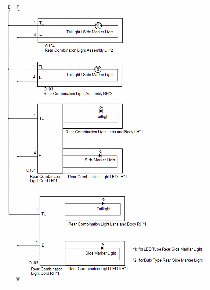
WIRING DIAGRAM
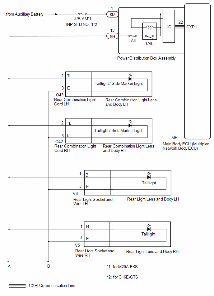
for Hatchback
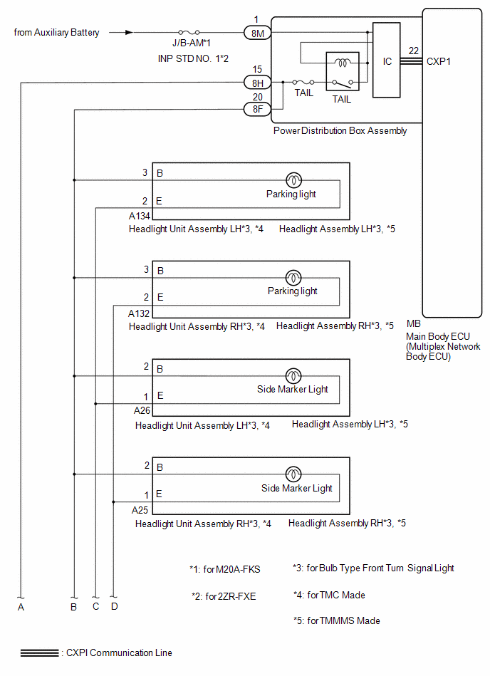
for Sedan
CAUTION / NOTICE / HINT
NOTICE:
- Inspect the fuses for circuits related to this system before performing the following procedure.
-
Before replacing the main body ECU (multiplex network body ECU), refer to Registration.
for HV Model: Click here
![2023 - 2025 MY Corolla Corolla HV [09/2022 - ]; THEFT DETERRENT / KEYLESS ENTRY: SMART KEY SYSTEM (for Start Function, HV Model): REGISTRATION](/t3Portal/stylegraphics/info.gif)
for Gasoline Model: Click here
-
First perform the communication function inspections in How to Proceed with Troubleshooting to confirm that there are no CXPI communication malfunctions before troubleshooting this symptom.
Click here
PROCEDURE
|
1. |
PERFORM ACTIVE TEST USING GTS |
(a) Perform the Active Test according to the display on the GTS.
Body Electrical > Main Body > Active Test
|
Tester Display |
Measurement Item |
Control Range |
Diagnostic Note |
|---|---|---|---|
|
Taillight / Clearance Light |
Taillights/parking lights |
OFF or ON |
- |
Body Electrical > Main Body > Active Test
|
Tester Display |
|---|
|
Taillight / Clearance Light |
OK:
Taillights, accessory lights*1, parking lights*2 and side marker lights illuminate.
- *1: w/ Accessory Light
- *2: for Sedan, for Bulb Type Turn Signal Light
| OK |

|
PROCEED TO NEXT SUSPECTED AREA SHOWN IN PROBLEM SYMPTOMS TABLE
|
|

|
2. |
CHECK HARNESS AND CONNECTOR (POWER SOURCE - POWER DISTRIBUTION BOX ASSEMBLY) |
(a) Disconnect the 8M power distribution box assembly connector.
(b) Measure the voltage according to the value(s) in the table below.
Standard Voltage:
|
Tester Connection |
Condition |
Specified Condition |
|---|---|---|
|
8M-1 - Body ground |
Always |
11 to 14 V |
| NG |
|
REPAIR OR REPLACE HARNESS OR CONNECTOR |
|
|
3. |
CONFIRM MODEL |
(a) Choose the model to be inspected.
|
Result |
Proceed to |
|---|---|
|
for Hatchback |
A |
|
for Sedan |
B |
| B |
|
|
|
4. |
CHECK HARNESS AND CONNECTOR (TAILLIGHT RELAY CIRCUIT) |
(a) Disconnect the 8H power distribution box assembly connector.
(b) Disconnect the O43 rear combination light cord LH connector.
(c) Disconnect the O42 rear combination light cord RH connector.
(d) Disconnect the V8 rear light socket and wire LH connector.
(e) Disconnect the V5 rear light socket and wire RH connector.
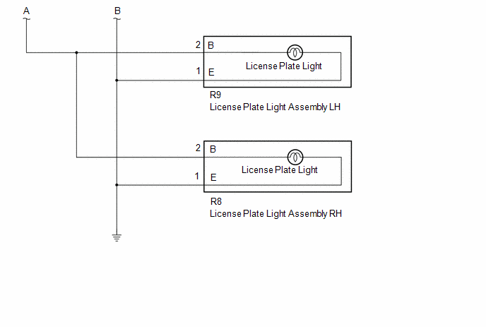
(f) Disconnect the R9 license plate light assembly LH connector.
(g) Disconnect the R8 license plate light assembly RH connector.
(h) Measure the resistance according to the value(s) in the table below.
Standard Resistance:
|
Tester Connection |
Condition |
Specified Condition |
|---|---|---|
|
8H-15 - O43-2 (TL) |
Always |
Below 1 Ω |
|
8H-15 or O43-2 (TL) - Body ground |
Always |
10 kΩ or higher |
| NG |
|
REPAIR OR REPLACE HARNESS OR CONNECTOR |
|
|
5. |
CHECK POWER DISTRIBUTION BOX ASSEMBLY |
(a) Connect the 8M power distribution box assembly connector.
(b) Connect the 8H power distribution box assembly connector.
(c) Turn the light control switch to the tail position.
(d) Measure the voltage according to the value(s) in the table below.
Standard Voltage:
|
Tester Connection |
Condition |
Specified Condition |
|---|---|---|
|
O43-2 (TL) - Body ground |
Ignition switch off |
11 to 14 V |
| NG |
|
|
|
6. |
CHECK REAR COMBINATION LIGHT CORD LH |
(a) Connect the O43 rear combination light cord LH connector.
(b) Turn the light control switch to the tail position.
(c) Measure the voltage according to the value(s) in the table below.
Standard Voltage:
|
Tester Connection |
Condition |
Specified Condition |
|---|---|---|
|
O42-2 (TL), V8-1 (B), V5-1 (B), R9-2 (B) or R8-2 (B) - Body ground |
Always |
11 to 14 V |
| NG |
|
|
|
7. |
CHECK REAR COMBINATION LIGHT CORD RH |
(a) Connect the O42 rear combination light cord RH connector.
(b) Turn the light control switch to the tail position.
(c) Measure the voltage according to the value(s) in the table below.
Standard Voltage:
|
Tester Connection |
Condition |
Specified Condition |
|---|---|---|
|
V8-1 (B), V5-1 (B), R9-2 (B) or R8-2 (B) - Body ground |
Always |
11 to 14 V |
| NG |
|
|
|
8. |
CHECK REAR LIGHT SOCKET AND WIRE LH |
(a) Connect the V8 rear light socket and wire LH connector.
(b) Turn the light control switch to the tail position.
(c) Measure the voltage according to the value(s) in the table below.
Standard Voltage:
|
Tester Connection |
Condition |
Specified Condition |
|---|---|---|
|
V5-1 (B), R9-2 (B) or R8-2 (B) - Body ground |
Always |
11 to 14 V |
| NG |
|
|
|
9. |
CHECK REAR LIGHT SOCKET AND WIRE RH |
(a) Connect the V5 rear light socket and wire RH connector.
(b) Turn the light control switch to the tail position.
(c) Measure the voltage according to the value(s) in the table below.
Standard Voltage:
|
Tester Connection |
Condition |
Specified Condition |
|---|---|---|
|
R9-2 (B) or R8-2 (B) - Body ground |
Always |
11 to 14 V |
| NG |
|
|
|
10. |
CHECK LICENSE PLATE LIGHT ASSEMBLY LH |
(a) Connect the R9 license plate light assembly LH connector.
(b) Turn the light control switch to the tail position.
(c) Measure the voltage according to the value(s) in the table below.
Standard Voltage:
|
Tester Connection |
Condition |
Specified Condition |
|---|---|---|
|
R8-2 (B) - Body ground |
Always |
11 to 14 V |
| NG |
|
|
|
11. |
CHECK LICENSE PLATE LIGHT ASSEMBLY RH |
(a) Disconnect the R9 license plate light assembly LH connector.
(b) Connect the R8 license plate light assembly RH connector.
(c) Turn the light control switch to the tail position.
(d) Measure the voltage according to the value(s) in the table below.
Standard Voltage:
|
Tester Connection |
Condition |
Specified Condition |
|---|---|---|
|
R9-2 (B) - Body ground |
Always |
11 to 14 V |
| OK |
|
PROCEED TO NEXT SUSPECTED AREA SHOWN IN PROBLEM SYMPTOMS TABLE
|
| NG |
|
|
12. |
CHECK REAR LIGHT LENS AND BODY RH |
(a) Disconnect the rear light lens and body RH connector.
(b) Turn the light control switch to the tail position.
(c) Measure the voltage according to the value(s) in the table below.
Standard Voltage:
|
Tester Connection |
Condition |
Specified Condition |
|---|---|---|
|
R9-2 (B) or R8-2 (B) - Body ground |
Always |
11 to 14 V |
| OK |
|
| NG |
|
|
13. |
CHECK REAR LIGHT LENS AND BODY LH |
(a) Disconnect the rear light lens and body LH connector.
(b) Turn the light control switch to the tail position.
(c) Measure the voltage according to the value(s) in the table below.
Standard Voltage:
|
Tester Connection |
Condition |
Specified Condition |
|---|---|---|
|
V5-1 (B), R9-2 (B) or R8-2 (B) - Body ground |
Always |
11 to 14 V |
| OK |
|
| NG |
|
|
14. |
CHECK REAR COMBINATION LIGHT LENS AND BODY RH |
(a) Disconnect the rear combination light lens and body RH connector.
(b) Turn the light control switch to the tail position.
(c) Measure the voltage according to the value(s) in the table below.
Standard Voltage:
|
Tester Connection |
Condition |
Specified Condition |
|---|---|---|
|
V8-1 (B), V5-1 (B), R9-2 (B) or R8-2 (B) - Body ground |
Always |
11 to 14 V |
| OK |
|
| NG |
|
|
15. |
CHECK REAR COMBINATION LIGHT LENS AND BODY LH |
(a) Disconnect the rear combination light lens and body LH connector.
(b) Turn the light control switch to the tail position.
(c) Measure the voltage according to the value(s) in the table below.
Standard Voltage:
|
Tester Connection |
Condition |
Specified Condition |
|---|---|---|
|
O42-2 (TL), V8-1 (B), V5-1 (B), R9-2 (B) or R8-2 (B) - Body ground |
Always |
11 to 14 V |
| OK |
|
| NG |
|
|
16. |
CONFIRM MODEL |
(a) Choose the model to be inspected.
|
Result |
Proceed to |
|---|---|
|
for Bulb Type Front Turn Signal Light or w/ Accessory Light |
A |
|
for LED Type Front Turn Signal Light or w/o Accessory Light |
B |
| B |
|
|
|
17. |
CHECK HARNESS AND CONNECTOR (TAILLIGHT RELAY CIRCUIT) |
(a) Disconnect the 8F power distribution box assembly connector.
(b) Disconnect the A134 headlight unit assembly LH connector.*1, *3
(c) Disconnect the A134 headlight assembly LH connector.*1, *4
(d) Disconnect the A132 headlight unit assembly RH connector.*1, *3
(e) Disconnect the A132 headlight assembly RH connector.*1, *4
(f) Disconnect the A26 headlight unit assembly LH connector.*1, *3
(g) Disconnect the A26 headlight assembly LH connector.*1, *4
(h) Disconnect the A25 headlight unit assembly RH connector.*1, *3
(i) Disconnect the A25 headlight assembly RH connector.*1, *4
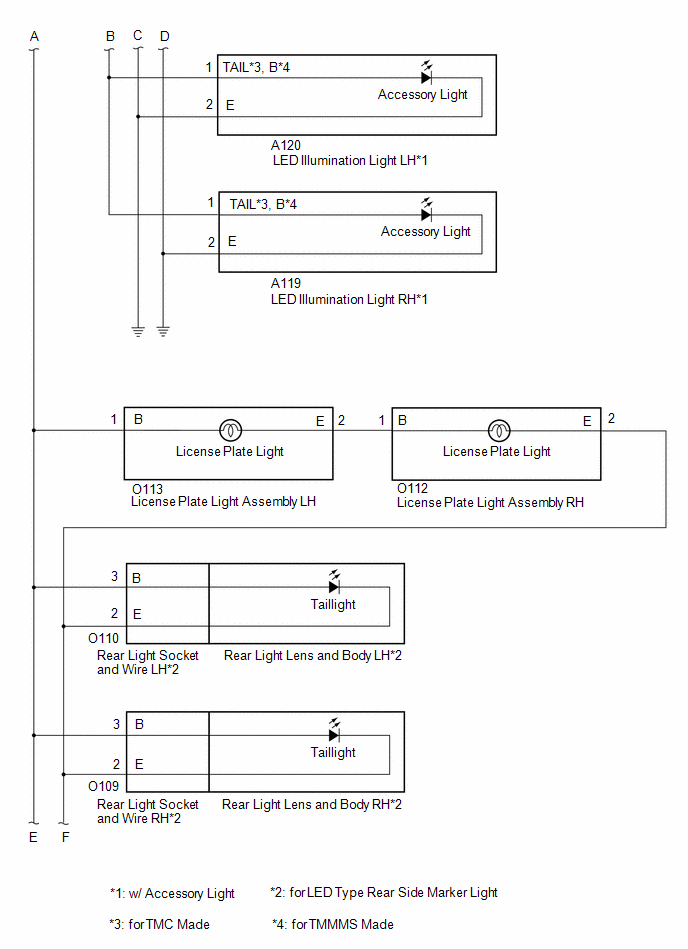
(j) Disconnect the A120 LED illumination light LH connector.*2
(k) Disconnect the A119 LED illumination light RH connector.*2
(l) Measure the resistance according to the value(s) in the table below.
Standard Resistance:
|
Tester Connection |
Condition |
Specified Condition |
|---|---|---|
|
8F-20 - A134-3 (B)*1 |
Always |
Below 1 Ω |
|
8F-20 - A120-1 (TAIL*3, B*4)*2 |
Always |
Below 1 Ω |
|
8F-20, A134-3 (B)*1 or A120-1(TAIL*3, *4)*2 - Body ground |
Always |
10 kΩ or higher |
- *1: for Bulb Type Front Turn Signal Light
- *2: w/ Accessory Light
- *3: for TMC Made
- *4: for TMMMS Made
| NG |
|
REPAIR OR REPLACE HARNESS OR CONNECTOR |
|
|
18. |
CHECK POWER DISTRIBUTION BOX ASSEMBLY |
(a) Connect the 8M power distribution box assembly connector.
(b) Connect the 8F power distribution box assembly connector.
(c) Turn the light control switch to the tail position.
(d) Measure the voltage according to the value(s) in the table below.
Standard Voltage:
|
Tester Connection |
Condition |
Specified Condition |
|---|---|---|
|
A134-3 (B) - Body ground*1 |
Ignition switch off |
11 to 14 V |
|
A120-1 (TAIL) - Body ground*2 |
Ignition switch off |
11 to 14 V |
- *1: for Bulb Type Front Turn Signal Light
- *2: w/ Accessory Light
| NG |
|
|
|
19. |
CONFIRM MODEL |
(a) Choose the model to be inspected.
|
Result |
Proceed to |
|---|---|
|
for Bulb Type Front Turn Signal Light |
A |
|
for LED Type Front Turn Signal Light |
B |
| B |
|
|
|
20. |
CONFIRM MODEL |
(a) Choose the model to be inspected.
|
Result |
Proceed to |
|---|---|
|
for TMC Made |
A |
|
for TMMMS Made |
B |
| B |
|
|
|
21. |
CHECK HEADLIGHT UNIT ASSEMBLY LH |
(a) Connect the 8F power distribution box assembly connector.
(b) Connect the A134 headlight unit assembly LH connector.
(c) Turn the light control switch to the tail position.
(d) Measure the voltage according to the value(s) in the table below.
Standard Voltage:
|
Tester Connection |
Condition |
Specified Condition |
|---|---|---|
|
A132-3 (B), A26-2 (B) or A25-2 (B) - Body ground |
Always |
11 to 14 V |
| NG |
|
|
|
22. |
CHECK HEADLIGHT UNIT ASSEMBLY RH |
(a) Connect the A132 headlight unit assembly RH connector.
(b) Turn the light control switch to the tail position.
(c) Measure the voltage according to the value(s) in the table below.
Standard Voltage:
|
Tester Connection |
Condition |
Specified Condition |
|---|---|---|
|
A26-2 (B) or A25-2 (B) - Body ground |
Always |
11 to 14 V |
| NG |
|
|
|
23. |
CHECK HEADLIGHT UNIT ASSEMBLY LH |
(a) Connect the A26 headlight unit assembly LH connector.
(b) Turn the light control switch to the tail position.
(c) Measure the voltage according to the value(s) in the table below.
Standard Voltage:
|
Tester Connection |
Condition |
Specified Condition |
|---|---|---|
|
A25-2 (B) - Body ground |
Always |
11 to 14 V |
| NG |
|
|
|
24. |
CHECK HEADLIGHT UNIT ASSEMBLY RH |
(a) Disconnect the A26 headlight unit assembly LH connector..
(b) Connect the A25 headlight unit assembly RH connector.
(c) Turn the light control switch to the tail position.
(d) Measure the voltage according to the value(s) in the table below.
Standard Voltage:
|
Tester Connection |
Condition |
Specified Condition |
|---|---|---|
|
A26-2 (B) - Body ground |
Always |
11 to 14 V |
| NG |
|
|
|
25. |
CONFIRM MODEL |
(a) Choose the model to be inspected.
|
Result |
Proceed to |
|---|---|
|
w/ Accessory Light |
A |
|
w/o Accessory Light |
B |
| A |
|
| B |
|
|
26. |
CHECK HEADLIGHT ASSEMBLY LH |
(a) Connect the 8H power distribution box assembly connector.
(b) Connect the A134 headlight assembly LH connector.
(c) Turn the light control switch to the tail position.
(d) Measure the voltage according to the value(s) in the table below.
Standard Voltage:
|
Tester Connection |
Condition |
Specified Condition |
|---|---|---|
|
A132-3 (B), A26-2 (B) or A25-2 (B) - Body ground |
Always |
11 to 14 V |
| NG |
|
|
|
27. |
CHECK HEADLIGHT ASSEMBLY RH |
(a) Connect the A132 headlight assembly RH connector.
(b) Turn the light control switch to the tail position.
(c) Measure the voltage according to the value(s) in the table below.
Standard Voltage:
|
Tester Connection |
Condition |
Specified Condition |
|---|---|---|
|
A26-2 (B) or A25-2 (B) - Body ground |
Always |
11 to 14 V |
| NG |
|
|
|
28. |
CHECK HEADLIGHT ASSEMBLY LH |
(a) Connect the A26 headlight assembly LH connector.
(b) Turn the light control switch to the tail position.
(c) Measure the voltage according to the value(s) in the table below.
Standard Voltage:
|
Tester Connection |
Condition |
Specified Condition |
|---|---|---|
|
A25-2 (B) - Body ground |
Always |
11 to 14 V |
| NG |
|
|
|
29. |
CHECK HEADLIGHT ASSEMBLY RH |
(a) Disconnect the A26 headlight assembly LH connector..
(b) Connect the A25 headlight assembly RH connector.
(c) Turn the light control switch to the tail position.
(d) Measure the voltage according to the value(s) in the table below.
Standard Voltage:
|
Tester Connection |
Condition |
Specified Condition |
|---|---|---|
|
A26-2 (B) - Body ground |
Always |
11 to 14 V |
| NG |
|
|
|
30. |
CONFIRM MODEL |
(a) Choose the model to be inspected.
|
Result |
Proceed to |
|---|---|
|
w/ Accessory Light |
A |
|
w/o Accessory Light |
B |
| A |
|
| B |
|
|
31. |
CHECK LED ILLUMINATION LIGHT LH |
(a) Connect the 8F power distribution box assembly connector.
(b) Connect the A120 LED illumination light LH connector.
(c) Turn the light control switch to the tail position.
(d) Measure the voltage according to the value(s) in the table below.
Standard Voltage:
|
Tester Connection |
Condition |
Specified Condition |
|---|---|---|
|
A119-1 (TAIL*1, B*2) - Body ground |
Always |
11 to 14 V |
- *1: for TMC Made
- *2: for TMMMS Made
| NG |
|
|
|
32. |
CHECK LED ILLUMINATION LIGHT RH |
(a) Disconnect the A120 LED illumination light LH connector.
(b) Connect the A119 LED illumination light RH connector.
(c) Turn the light control switch to the tail position.
(d) Measure the voltage according to the value(s) in the table below.
Standard Voltage:
|
Tester Connection |
Condition |
Specified Condition |
|---|---|---|
|
A120-1 (TAIL*1, B*2) - Body ground |
Always |
11 to 14 V |
- *1: for TMC Made
- *2: for TMMMS Made
| OK |
|
| NG |
|
|
33. |
CHECK HARNESS AND CONNECTOR (TAILLIGHT RELAY CIRCUIT) |
(a) Disconnect the 8H power distribution box assembly connector.
(b) Disconnect the O113 license plate light assembly LH connector.
(c) Disconnect the O110 rear light socket and wire LH connector.*1
(d) Disconnect the O109 rear light socket and wire RH connector.*1
(e) Disconnect the O104 rear combination light cord LH connector.*1
(f) Disconnect the O103 rear combination light cord RH connector.*1
(g) Disconnect the O104 rear combination light assembly LH connector.*2
(h) Disconnect the O103 rear combination light assembly RH connector.*2
(i) Measure the resistance according to the value(s) in the table below.
Standard Resistance:
|
Tester Connection |
Condition |
Specified Condition |
|---|---|---|
|
8H-15 - O113-1 (B) |
Always |
Below 1 Ω |
|
8H-15 or O113-1 (B) - Body ground |
Always |
10 kΩ or higher |
- *1: for LED Type Rear Side Marker Light
- *2: for Bulb Type Rear Side Marker Light
| NG |
|
REPAIR OR REPLACE HARNESS OR CONNECTOR |
|
|
34. |
CHECK POWER DISTRIBUTION BOX ASSEMBLY |
(a) Connect the 8M power distribution box assembly connector.
(b) Connect the 8H power distribution box assembly connector.
(c) Turn the light control switch to the tail position.
(d) Measure the voltage according to the value(s) in the table below.
Standard Voltage:
|
Tester Connection |
Condition |
Specified Condition |
|---|---|---|
|
O113-1 (B) - Body ground |
Ignition switch off |
11 to 14 V |
| NG |
|
|
|
35. |
CHECK LICENSE PLATE LIGHT ASSEMBLY LH |
(a) Connect the O113 license plate light assembly LH connector.
(b) Turn the light control switch to the tail position.
(c) Measure the voltage according to the value(s) in the table below.
Standard Voltage:
|
Tester Connection |
Condition |
Specified Condition |
|---|---|---|
|
O110-3 (B)*, O109-3 (B)*, O104-1 (TL) or O103-1 (TL) - Body ground |
Always |
11 to 14 V |
- *: for LED Type Rear Side Marker Light
| NG |
|
|
|
36. |
CONFIRM MODEL |
(a) Choose the model to be inspected.
|
Result |
Proceed to |
|---|---|
|
for LED Type Rear Side Marker Light |
A |
|
for Bulb Type Rear Side Marker Light |
B |
| B |
|
|
|
37. |
CHECK REAR LIGHT SOCKET AND WIRE LH |
(a) Connect the O110 rear light socket and wire LH connector.
(b) Turn the light control switch to the tail position.
(c) Measure the voltage according to the value(s) in the table below.
Standard Voltage:
|
Tester Connection |
Condition |
Specified Condition |
|---|---|---|
|
O109-3 (B), O104-1 (TL) or O103-1 (TL) - Body ground |
Always |
11 to 14 V |
| NG |
|
|
|
38. |
CHECK REAR LIGHT SOCKET AND WIRE RH |
(a) Connect the O109 rear light socket and wire RH connector.
(b) Turn the light control switch to the tail position.
(c) Measure the voltage according to the value(s) in the table below.
Standard Voltage:
|
Tester Connection |
Condition |
Specified Condition |
|---|---|---|
|
O104-1 (TL) or O103-1 (TL) - Body ground |
Always |
11 to 14 V |
| NG |
|
|
|
39. |
CHECK REAR COMBINATION LIGHT CORD LH |
(a) Connect the O104 rear combination light cord LH connector.
(b) Turn the light control switch to the tail position.
(c) Measure the voltage according to the value(s) in the table below.
Standard Voltage:
|
Tester Connection |
Condition |
Specified Condition |
|---|---|---|
|
O103-1 (TL) - Body ground |
Always |
11 to 14 V |
| NG |
|
|
|
40. |
CHECK REAR COMBINATION LIGHT CORD RH |
(a) Disconnect the O104 rear combination light cord LH connector.
(b) Connect the O103 rear combination light cord RH connector.
(c) Turn the light control switch to the tail position.
(d) Measure the voltage according to the value(s) in the table below.
Standard Voltage:
|
Tester Connection |
Condition |
Specified Condition |
|---|---|---|
|
O104-1 (TL) - Body ground |
Always |
11 to 14 V |
| OK |
|
PROCEED TO NEXT SUSPECTED AREA SHOWN IN PROBLEM SYMPTOMS TABLE
|
|
|
41. |
CHECK REAR COMBINATION LIGHT LENS AND BODY RH |
(a) Disconnect the rear combination light lens and body RH connector.
(b) Turn the light control switch to the tail position.
(c) Measure the voltage according to the value(s) in the table below.
Standard Voltage:
|
Tester Connection |
Condition |
Specified Condition |
|---|---|---|
|
O104-1 (TL) - Body ground |
Always |
11 to 14 V |
| OK |
|
|
|
42. |
CHECK REAR COMBINATION LIGHT LED RH |
(a) Disconnect the rear combination light LED RH connector.
(b) Turn the light control switch to the tail position.
(c) Measure the voltage according to the value(s) in the table below.
Standard Voltage:
|
Tester Connection |
Condition |
Specified Condition |
|---|---|---|
|
O104-1 (TL) - Body ground |
Always |
11 to 14 V |
| OK |
|
| NG |
|
|
43. |
CHECK REAR COMBINATION LIGHT LENS AND BODY LH |
(a) Disconnect the rear combination light lens and body LH connector.
(b) Turn the light control switch to the tail position.
(c) Measure the voltage according to the value(s) in the table below.
Standard Voltage:
|
Tester Connection |
Condition |
Specified Condition |
|---|---|---|
|
O103-1 (TL) - Body ground |
Always |
11 to 14 V |
| OK |
|
|
|
44. |
CHECK REAR COMBINATION LIGHT LED LH |
(a) Disconnect the rear combination light LED LH connector.
(b) Turn the light control switch to the tail position.
(c) Measure the voltage according to the value(s) in the table below.
Standard Voltage:
|
Tester Connection |
Condition |
Specified Condition |
|---|---|---|
|
O103-1 (TL) - Body ground |
Always |
11 to 14 V |
| OK |
|
| NG |
|
|
45. |
CHECK REAR LIGHT LENS AND BODY RH |
(a) Disconnect the rear light lens and body RH connector.
(b) Turn the light control switch to the tail position.
(c) Measure the voltage according to the value(s) in the table below.
Standard Voltage:
|
Tester Connection |
Condition |
Specified Condition |
|---|---|---|
|
O104-1 (TL) or O103-1 (TL) - Body ground |
Always |
11 to 14 V |
| OK |
|
| NG |
|
|
46. |
CHECK REAR LIGHT LENS AND BODY LH |
(a) Disconnect the rear light lens and body LH connector.
(b) Turn the light control switch to the tail position.
(c) Measure the voltage according to the value(s) in the table below.
Standard Voltage:
|
Tester Connection |
Condition |
Specified Condition |
|---|---|---|
|
O109-3 (B), O104-1 (TL) or O103-1 (TL) - Body ground |
Always |
11 to 14 V |
| OK |
|
| NG |
|
|
47. |
CHECK REAR COMBINATION LIGHT ASSEMBLY LH |
(a) Connect the O104 rear combination light assembly LH connector.
(b) Turn the light control switch to the tail position.
(c) Measure the voltage according to the value(s) in the table below.
Standard Voltage:
|
Tester Connection |
Condition |
Specified Condition |
|---|---|---|
|
O103-1 (TL) - Body ground |
Always |
11 to 14 V |
| NG |
|
|
|
48. |
CHECK REAR COMBINATION LIGHT ASSEMBLY RH |
(a) Disconnect the O104 rear combination light assembly LH connector.
(b) Connect the O103 rear combination light assembly RH connector.
(c) Turn the light control switch to the tail position.
(d) Measure the voltage according to the value(s) in the table below.
Standard Voltage:
|
Tester Connection |
Condition |
Specified Condition |
|---|---|---|
|
O104-1 (TL) - Body ground |
Always |
11 to 14 V |
| OK |
|
PROCEED TO NEXT SUSPECTED AREA SHOWN IN PROBLEM SYMPTOMS TABLE
|
| NG |
|
|
|
|