- Hybrid Control system cannot be started*1
- Engine cannot be started*2
| Last Modified: 05-13-2024 | 6.11:8.1.0 | Doc ID: RM10000000295B5 |
| Model Year Start: 2023 | Model: GR Corolla | Prod Date Range: [11/2022 - ] |
| Title: THEFT DETERRENT / KEYLESS ENTRY: IMMOBILISER SYSTEM (w/o Smart Key System): B279986; Engine Immobiliser System Signal (Some Circuit Quantity, Reported via Serial Data) Invalid; 2023 - 2025 MY Corolla Corolla Hatchback Corolla HV GR Corolla [11/2022 - ] | ||
|
DTC |
B279986 |
Engine Immobiliser System Signal (Some Circuit Quantity, Reported via Serial Data) Invalid |
DESCRIPTION
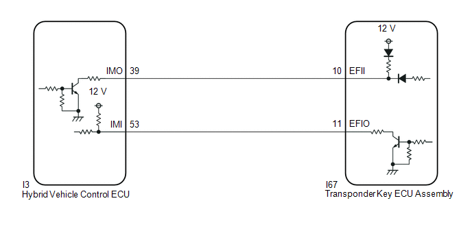
- The hybrid vehicle control ECU stores this DTC when a communication line between the hybrid vehicle control ECU and transponder key ECU assembly is malfunctioning or the communication ID of the hybrid vehicle control ECU and transponder key ECU assembly do not match.*1
-
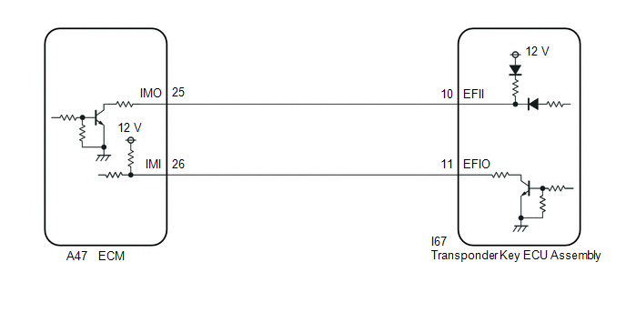
The ECM stores this DTC when a communication line between the ECM and transponder key ECU assembly is malfunctioning or the communication ID of the ECM and transponder key ECU assembly do not match.*2
- *1: for HV Model
- *2: for Gasoline Model
|
DTC No. |
Detection Item |
DTC Detection Condition |
Trouble Area |
Note |
|---|---|---|---|---|
|
B279986 |
Engine Immobiliser System Signal (Some Circuit Quantity, Reported via Serial Data) Invalid |
One of the following conditions is met:
|
|
DTC Output Confirmation Operation:
|
- *1: for HV Model
- *2: for Gasoline Model
Vehicle Condition and Fail-safe Operation when Malfunction Detected
|
Vehicle Condition when Malfunction Detected |
Fail-safe Operation when Malfunction Detected |
|---|---|
|
|
- |
- *1: for HV Model
- *2: for Gasoline Model
Related Data List and Active Test
|
DTC No. |
Data List and Active Test |
|---|---|
|
B279986 |
- |
WIRING DIAGRAM
for HV Model
for Gasoline Model
CAUTION / NOTICE / HINT
NOTICE:
-
If the transponder key ECU assembly or hybrid vehicle control ECU is replaced, refer to Registration.*1
If the transponder key ECU assembly or ECM is replaced, refer to Registration.*2
Click here
![2023 - 2025 MY Corolla Corolla Hatchback Corolla HV GR Corolla [11/2022 - ]; THEFT DETERRENT / KEYLESS ENTRY: IMMOBILISER SYSTEM (w/o Smart Key System): REGISTRATION](/t3Portal/stylegraphics/info.gif)
-
After repair, confirm that no DTCs are output by performing "DTC Output Confirmation Operation".
- *1: for HV Model
- *2: for Gasoline Model
HINT:
If transponder key ECU assembly DTCs are output simultaneously, troubleshoot the transponder key ECU assembly DTCs first.
PROCEDURE
|
1. |
REGISTER ECU COMMUNICATION ID |
(a) Reregister the ECU communication ID.
|
Result |
Proceed to |
|---|---|
|
for HV Model |
A |
|
for Gasoline Model |
B |
| B |

|
|

|
2. |
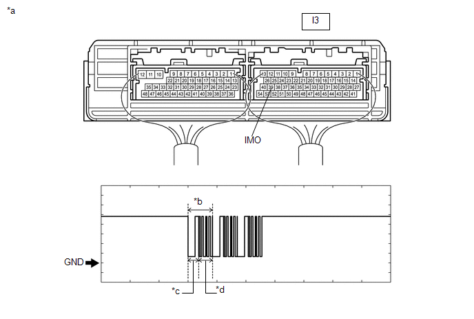
INSPECT HYBRID VEHICLE CONTROL ECU (TERMINAL IMO) |
(a) Using an oscilloscope, check the waveform.
|
*a |
Component with harness connected (Hybrid Vehicle Control ECU) |
*b |
Waveform |
|
*c |
Approximately 160 ms. |
*d |
Approximately 270 ms. |
OK
|
Tester Connection |
Condition |
Tool Setting |
Specified Condition |
|---|---|---|---|
|
I3-39 (IMO) - Body ground |
Within 3 seconds of starter operation and initial combustion, or within 3 seconds of ignition switch first being turned to ON after cable disconnected and reconnected to negative (-) auxiliary battery terminal |
2 V/DIV., 500 ms./DIV. |
Pulse generation (See waveform) |
OK:
Waveform is similar to that shown in the illustration.
|
Result |
Proceed to |
|---|---|
|
OK |
A |
|
NG (Terminal IMO stuck low (2.4 V or less)) |
B |
|
NG (Terminal IMO stuck high (12 V) or abnormal waveform) |
C |
| B |
|
| C |
|
|
|
3. |
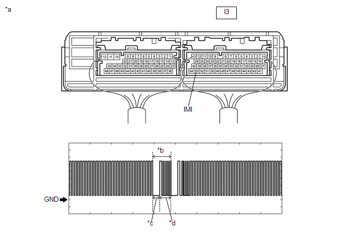
INSPECT HYBRID VEHICLE CONTROL ECU (TERMINAL IMI) |
(a) Using an oscilloscope, check the waveform.
|
*a |
Component with harness connected (Hybrid Vehicle Control ECU) |
*b |
Waveform |
|
*c |
Approximately 160 ms. |
*d |
Approximately 270 ms. |
OK
|
Tester Connection |
Condition |
Tool Setting |
Specified Condition |
|---|---|---|---|
|
I3-53 (IMI) - Body ground |
Within 3 seconds of starter operation and initial combustion, or within 3 seconds of ignition switch first being turned to ON after cable disconnected and reconnected to negative (-) auxiliary battery terminal |
2 V/DIV., 500 ms./DIV. |
Pulse generation (See waveform) |
OK:
Waveform is similar to that shown in the illustration.
| NG |
|
|
|
4. |
REGISTER ECU COMMUNICATION ID |
(a) Reregister the ECU communication ID.
|
|
5. |
CHECK HYBRID CONTROL SYSTEM STARTS |
(a) Using a registered door control transmitter assembly, turn the ignition switch to ON.
(b) Check that the hybrid control system can be started 5 seconds after the ignition switch was turned to ON (IG).
OK:
Hybrid control system starts normally.
| OK |
|
END (COMMUNICATION ID REGISTRATION WAS DEFECTIVE) |
| NG |
|
|
6. |
CHECK HARNESS AND CONNECTOR (TRANSPONDER KEY ECU ASSEMBLY - HYBRID VEHICLE CONTROL ECU) |
(a) Disconnect the I67 transponder key ECU assembly connector.
(b) Disconnect the I3 hybrid vehicle control ECU connector.
(c) Measure the resistance according to the value(s) in the table below.
Standard Resistance:
|
Tester Connection |
Condition |
Specified Condition |
|---|---|---|
|
I67-11 (EFIO) - I3-53 (IMI) |
Always |
Below 1 Ω |
|
I67-11 (EFIO) or I3-53 (IMI) - Other terminals and body ground |
Always |
10 kΩ or higher |
| OK |
|
| NG |
|
REPAIR OR REPLACE HARNESS OR CONNECTOR |
|
7. |
INSPECT HYBRID VEHICLE CONTROL ECU (IMO TERMINAL VOLTAGE) |
(a) Disconnect the I3 hybrid vehicle control ECU connector.
(b) Measure the voltage according to the value(s) in the table below.
Standard Voltage:
|
Tester Connection |
Condition |
Result |
|---|---|---|
|
I3-39 (IMO) - Body ground |
Ignition switch turned to ON using registered door control transmitter assembly |
Terminal IMO stuck low (2.4 V or less) |
|
Terminal IMO stuck high (12 V) or abnormal waveform |
|
Result |
Proceed to |
|---|---|
|
Terminal IMO stuck low (2.4 V or less) |
A |
|
Terminal IMO stuck high (12 V) or abnormal waveform |
B |
| B |
|
|
|
8. |
CHECK HARNESS AND CONNECTOR (TRANSPONDER KEY ECU ASSEMBLY - HYBRID VEHICLE CONTROL ECU) |
(a) Disconnect the I67 transponder key ECU assembly connector.
(b) Measure the resistance according to the value(s) in the table below.
Standard Resistance:
|
Tester Connection |
Condition |
Specified Condition |
|---|---|---|
|
I67-10 (EFII) - I3-39 (IMO) |
Always |
Below 1 Ω |
|
I67-10 (EFII) or I3-39 (IMO) - Other terminals and body ground |
Always |
10 kΩ or higher |
| OK |
|
| NG |
|
REPAIR OR REPLACE HARNESS OR CONNECTOR |
|
9. |
CHECK HARNESS AND CONNECTOR (TRANSPONDER KEY ECU ASSEMBLY - HYBRID VEHICLE CONTROL ECU) |
(a) Disconnect the I67 transponder key ECU assembly connector.
(b) Disconnect the I3 hybrid vehicle control ECU connector.
(c) Measure the resistance according to the value(s) in the table below.
Standard Resistance:
|
Tester Connection |
Condition |
Specified Condition |
|---|---|---|
|
I67-10 (EFII) - I3-39 (IMO) |
Always |
Below 1 Ω |
|
I67-10 (EFII) or I3-39 (IMO) - Other terminals and body ground |
Always |
10 kΩ or higher |
| OK |
|
| NG |
|
REPAIR OR REPLACE HARNESS OR CONNECTOR |
|
10. |
INSPECT TRANSPONDER KEY ECU ASSEMBLY (TERMINAL EFII) |
(a) Using an oscilloscope, check the waveform.
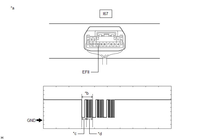
|
*a |
Component with harness connected (Transponder Key ECU Assembly) |
*b |
Waveform |
|
*c |
Approximately 160 ms. |
*d |
Approximately 270 ms. |
OK
|
Tester Connection |
Condition |
Tool Setting |
Specified Condition |
|---|---|---|---|
|
I67-10 (EFII) - Body ground |
Within 3 seconds of starter operation and initial combustion, or within 3 seconds of ignition switch first being turned to ON after cable disconnected and reconnected to negative (-) auxiliary battery terminal |
2 V/DIV., 500 ms./DIV. |
Pulse generation (See waveform) |
OK:
Waveform is similar to that shown in the illustration.
|
Result |
Proceed to |
|---|---|
|
OK |
A |
|
NG (Terminal EFII stuck low (2.4 V or less)) |
B |
|
NG (Terminal EFII stuck high (12 V) or abnormal waveform) |
C |
| B |
|
| C |
|
|
|
11. |
INSPECT TRANSPONDER KEY ECU ASSEMBLY (TERMINAL EFIO) |
(a) Using an oscilloscope, check the waveform.
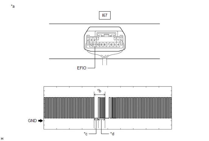
|
*a |
Component with harness connected (Transponder Key ECU Assembly) |
*b |
Waveform |
|
*c |
Approximately 160 ms. |
*d |
Approximately 270 ms. |
OK
|
Tester Connection |
Condition |
Tool Setting |
Specified Condition |
|---|---|---|---|
|
I67-11 (EFIO) - Body ground |
Within 3 seconds of starter operation and initial combustion, or within 3 seconds of ignition switch first being turned to ON after cable disconnected and reconnected to negative (-) auxiliary battery terminal |
2 V/DIV., 500 ms./DIV. |
Pulse generation (See waveform) |
OK:
Waveform is similar to that shown in the illustration.
| NG |
|
|
|
12. |
REGISTER ECU COMMUNICATION ID |
(a) Reregister the ECU communication ID.
|
|
13. |
CHECK WHETHER ENGINE STARTS |
(a) Using a registered door control transmitter assembly, turn the ignition switch to ON.
(b) Check that the engine starts 5 seconds after the ignition switch was turned to ON.
OK:
Engine starts normally.
| OK |
|
END (COMMUNICATION ID REGISTRATION WAS DEFECTIVE) |
| NG |
|
REPLACE ECM
|
|
14. |
CHECK HARNESS AND CONNECTOR (TRANSPONDER KEY ECU ASSEMBLY - ECM) |
(a) Disconnect the I67 transponder key ECU assembly connector.
(b) Disconnect the A47 ECM connector.
(c) Measure the resistance according to the value(s) in the table below.
Standard Resistance:
|
Tester Connection |
Condition |
Specified Condition |
|---|---|---|
|
I67-11 (EFIO) - A47-26 (IMI) |
Always |
Below 1 Ω |
|
I67-11 (EFIO) or A47-26 (IMI) - Other terminals and body ground |
Always |
10 kΩ or higher |
| OK |
|
| NG |
|
REPAIR OR REPLACE HARNESS OR CONNECTOR |
|
15. |
INSPECT ECM (IMO TERMINAL VOLTAGE) |
(a) Disconnect the A47 ECM connector.
(b) Measure the voltage according to the value(s) in the table below.
Standard Voltage:
|
Tester Connection |
Condition |
Result |
|---|---|---|
|
A47-25 (IMO) - Body ground |
Ignition switch turned to ON using registered door control transmitter assembly |
Terminal IMO stuck low (2.4 V or less) |
|
Terminal IMO stuck high (12 V) or abnormal waveform |
|
Result |
Proceed to |
|---|---|
|
Terminal IMO stuck low (2.4 V or less) |
A |
|
Terminal IMO stuck high (12 V) or abnormal waveform |
B |
| B |
|
REPLACE ECM
|
|
|
16. |
CHECK HARNESS AND CONNECTOR (TRANSPONDER KEY ECU ASSEMBLY - ECM) |
(a) Disconnect the I67 transponder key ECU assembly connector.
(b) Measure the resistance according to the value(s) in the table below.
Standard Resistance:
|
Tester Connection |
Condition |
Specified Condition |
|---|---|---|
|
I67-10 (EFII) - A47-25 (IMO) |
Always |
Below 1 Ω |
|
I67-10 (EFII) or A47-25 (IMO) - Other terminals and body ground |
Always |
10 kΩ or higher |
| OK |
|
| NG |
|
REPAIR OR REPLACE HARNESS OR CONNECTOR |
|
17. |
CHECK HARNESS AND CONNECTOR (TRANSPONDER KEY ECU ASSEMBLY - ECM) |
(a) Disconnect the I67 transponder key ECU assembly connector.
(b) Disconnect the A47 connector.
(c) Measure the resistance according to the value(s) in the table below.
Standard Resistance:
|
Tester Connection |
Condition |
Specified Condition |
|---|---|---|
|
I67-10 (EFII) - A47-25 (IMO) |
Always |
Below 1 Ω |
|
I67-10 (EFII) or A47-25 (IMO) - Other terminals and body ground |
Always |
10 kΩ or higher |
| OK |
|
REPLACE ECM
|
| NG |
|
REPAIR OR REPLACE HARNESS OR CONNECTOR |
|
|
|