- Hybrid control system cannot be started*1
- Engine cannot be started*2
| Last Modified: 01-27-2025 | 6.11:8.1.0 | Doc ID: RM10000000294YU |
| Model Year Start: 2023 | Model: GR Corolla | Prod Date Range: [09/2022 - ] |
| Title: THEFT DETERRENT / KEYLESS ENTRY: IMMOBILISER SYSTEM (w/o Smart Key System): B2780; Push Switch / Key Unlock Warning Switch Malfunction; 2023 - 2025 MY Corolla Corolla Hatchback Corolla HV GR Corolla [09/2022 - ] | ||
|
DTC |
B2780 |
Push Switch / Key Unlock Warning Switch Malfunction |
DESCRIPTION
This DTC is stored if the transponder key ECU assembly does not detect that the unlock warning switch assembly is on even when the ignition switch is ON.
|
DTC No. |
Detection Item |
DTC Detection Condition |
Trouble Area |
Note |
|---|---|---|---|---|
|
B2780 |
Push Switch / Key Unlock Warning Switch Malfunction |
The unlock warning switch assembly is not detected as being on when the ignition switch is ON (1 trip detection logic*). |
|
DTC Output Confirmation Operation:
|
- *: Only output while a malfunction is present.
Vehicle Condition and Fail-safe Operation when Malfunction Detected
|
Vehicle Condition when Malfunction Detected |
Fail-safe Operation when Malfunction Detected |
|---|---|
|
|
- |
- *1: for HV Model
- *2: for Gasoline Model
Related Data List and Active Test
|
DTC No. |
Data List and Active Test |
|---|---|
|
B2780 |
Key SW |
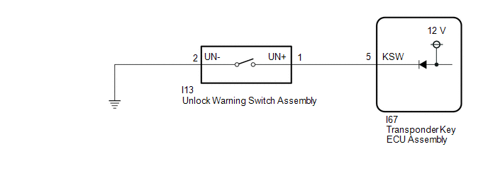
WIRING DIAGRAM
CAUTION / NOTICE / HINT
NOTICE:
-
If the transponder key ECU assembly is replaced, refer to Registration.
Click here
![2023 MY Corolla Corolla Hatchback Corolla HV GR Corolla [09/2022 - 11/2022]; THEFT DETERRENT / KEYLESS ENTRY: IMMOBILISER SYSTEM (w/o Smart Key System): REGISTRATION](/t3Portal/stylegraphics/info.gif)
- After repair, confirm that no DTCs are output by performing "DTC Output Confirmation Operation".
PROCEDURE
|
1. |
INSPECT UNLOCK WARNING SWITCH ASSEMBLY |
(a) Remove the unlock warning switch assembly.
Click here
(b) Inspect the unlock warning switch assembly.
Click here
| NG |

|
|

|
2. |
CHECK HARNESS AND CONNECTOR (UNLOCK WARNING SWITCH ASSEMBLY - TRANSPONDER KEY ECU ASSEMBLY - BODY GROUND) |
(a) Disconnect the I67 transponder key ECU assembly connector.
(b) Measure the resistance according to the value(s) in the table below.
Standard Resistance:
|
Tester Connection |
Condition |
Specified Condition |
|---|---|---|
|
I13-1 (UN+) - I67-5 (KSW) |
Always |
Below 1 Ω |
|
I13-2 (UN-) - Body ground |
Always |
Below 1 Ω |
|
I13-1 (UN+) or I67-5 (KSW) - Other terminals and body ground |
Always |
10 kΩ or higher |
| OK |
|
REPLACE TRANSPONDER KEY ECU ASSEMBLY
|
| NG |
|
REPAIR OR REPLACE HARNESS OR CONNECTOR |
|
|
|