- Wireless Door Lock Control System (for Gasoline Model with Smart Key System)
- Smart Key System (for Gasoline Model, Entry Function)
- Smart Key System (for Gasoline Model, Start Function)
- Steering lock function*1
| Last Modified: 01-27-2025 | 6.11:8.1.0 | Doc ID: RM1000000028LLM |
| Model Year Start: 2023 | Model: GR Corolla | Prod Date Range: [11/2022 - 09/2024] |
| Title: G16E-GTS (ENGINE MECHANICAL): ENGINE UNIT: REMOVAL; 2023 - 2025 MY GR Corolla [11/2022 - 09/2024] | ||
REMOVAL
CAUTION / NOTICE / HINT
The necessary procedures (adjustment, calibration, initialization or registration) that must be performed after parts are removed and installed, or replaced during engine unit removal/installation are shown below.
Necessary Procedure After Parts Removed/Installed/Replaced
|
Replaced Part or Performed Procedure |
Necessary Procedure |
Effect/Inoperative Function when Necessary Procedure not Performed |
Link |
|---|---|---|---|
| *1:w/ Steering Lock Function | |||
|
Replacement of ECM |
Perform Vehicle Identification Number (VIN) or frame number registration |
MIL illuminates |
|
|
ECU configuration |
- |
|
|
|
Update ECU security key |
Vehicle Control History (RoB) are stored |
|
|
|
Heavy Knock History |
- |
|
|
|
ECU communication ID registration (Immobiliser system) |
Engine start function |
|
|
|
Code registration (Smart Key System (for Gasoline Model, Start Function)) |
|
|
|
|
Inspection After Repair |
|
|
|
Front wheel alignment adjustment |
|
|
|
|
Tire |
ECU Data Initialization (When performing tire replacement after RoB code X2104 is output) |
Active Torque Split AWD System |
|
NOTICE:
This procedure includes the removal of small-head bolts. Refer to Small-Head Bolts of Basic Repair Hint to identify the small-head bolts.
Click here
![2019 - 2025 MY Corolla Corolla Hatchback Corolla HV GR Corolla [06/2018 - ]; INTRODUCTION: REPAIR INSTRUCTION: PRECAUTION](/t3Portal/stylegraphics/info.gif)
HINT:
When the cable is disconnected / reconnected to the auxiliary battery terminal, systems temporarily stop operating. However, each system has a function that completes learning the first time the system is used.
-
Learning completes when vehicle is driven
Effect/Inoperative Function When Necessary Procedures are not Performed
Necessary Procedures
Link
Front Camera System
Drive the vehicle straight ahead at 35 km/h (22 mph) or more for 5 seconds or more.
-
Learning completes when vehicle is operated normally
Effect/Inoperative Function When Necessary Procedures are not Performed
Necessary Procedures
Link
Power door lock control system
- Back door opener
Perform door unlock operation with door control switch or electrical key transmitter sub-assembly switch.
PROCEDURE
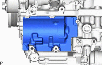
1. REMOVE COMPRESSOR ASSEMBLY WITH PULLEY
Click here
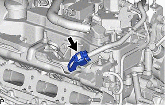
2. REMOVE FUEL TUBE SUB-ASSEMBLY
|
(a) Disengage the clamp. |
|
(b) Remove the fuel tube sub-assembly from the fuel pipe sub-assembly.
Click here
3. REMOVE NO. 2 AIR HOSE
|
(a) Loosen the hose clamp and remove the No. 2 air hose from the turbocharger sub-assembly. |
|
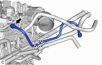
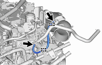
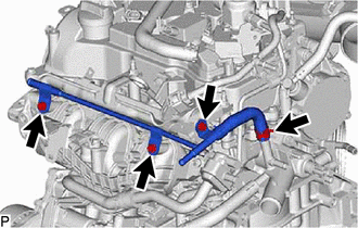
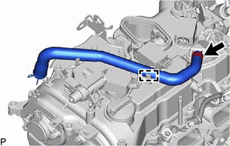
4. REMOVE NO. 6 WATER BY-PASS HOSE
|
(a) Slide the 2 clips and separate the No. 6 water by-pass hose. |
|
(b) Disengage the clamp and remove the No. 6 water by-pass hose from the No. 1 water hose clamp bracket.
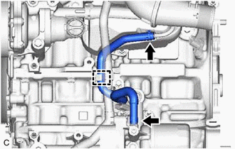
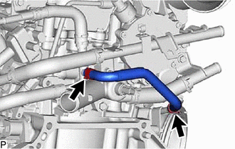
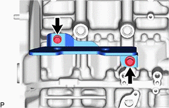
5. REMOVE NO. 5 WATER BY-PASS HOSE
|
(a) Slide the 2 clips and separate the No. 5 water by-pass hose. |
|
(b) Remove the bolt and No. 5 water by-pass hose from the crankshaft bearing cap.
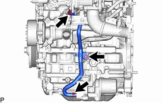
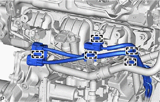
6. REMOVE NO. 3 VACUUM TRANSMITTING HOSE
|
(a) Disengage the 2 clamp and remove the No. 3 vacuum transmitting hose. |
|
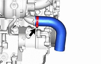
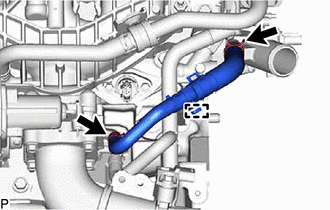
7. REMOVE NO. 1 TURBO WATER HOSE
|
(a) Slide the 2 clips and remove the No. 1 turbo water hose. |
|
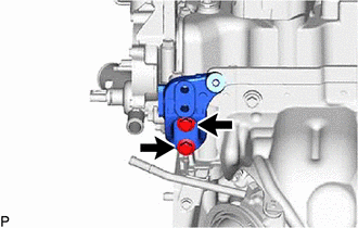
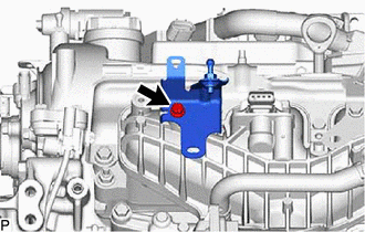
8. REMOVE NO. 1 WATER BY-PASS PIPE
|
(a) Slide the clip and separate the No. 1 water by-pass pipe. |
|
(b) Remove the bolt, nut and No. 1 water by-pass pipe.
9. REMOVE NO. 3 WATER BY-PASS PIPE
|
(a) Remove the bolt and separate the No. 3 water by-pass pipe. |
|
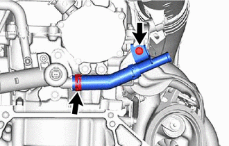
(b) Slide the clip and remove the No. 3 water by-pass pipe.
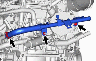
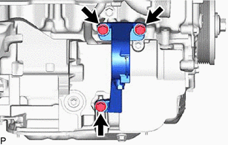
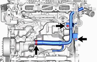
10. REMOVE NO. 4 WATER BY-PASS PIPE
|
(a) Remove the 3 bolts and separate the No. 4 water by-pass pipe. |
|
(b) Slide the clip and remove the No. 4 water by-pass pipe.
11. REMOVE WATER BY-PASS HOSE ASSEMBLY
|
(a) Disengage the clamp. |
|
(b) Slide the 2 clips and remove the water by-pass hose assembly.
12. REMOVE E.F.I. VACUUM SENSOR ASSEMBLY (MANIFOLD ABSOLUTE PRESSURE SENSOR)
Click here
13. REMOVE VACUUM SENSOR ASSEMBLY
Click here
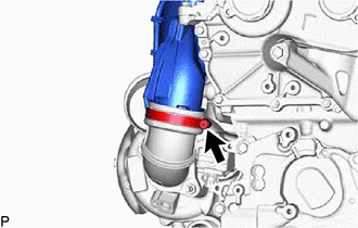
14. REMOVE INTAKE AIR PIPE
|
(a) Separate the No.1 vacuum transmitting hose. |
|
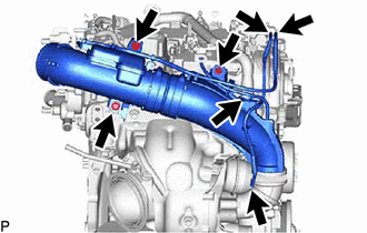
(b) Separate the No. 2 vacuum transmitting hose.
(c) Separate the ventilation hose.
(d) Remove the e3 bolts.
|
(e) Loosen the hose clamp and remove the intake air pipe from the . |
|
15. REMOVE ENGINE HANGER BRACKET
|
(a) Remove the 2 bolts and engine hanger bracket from the cylinder head sub-assembly. |
|
16. REMOVE DRIVE SHAFT BEARING BRACKET
|
(a) Remove the 3 bolts and drive shaft bearing bracket from the cylinder block sub-assembly. |
|
17. REMOVE NO. 4 CYLINDER BLOCK INSULATOR
|
(a) Remove the 2 bolts and No. 4 cylinder block insulator. |
|
18. REMOVE NO. 1 TURBO INSULATOR
Click here
19. REMOVE TURBOCHARGER SUB-ASSEMBLY
|
(a) Remove the 2 bolts and separate the outlet turbo oil pipe. |
|
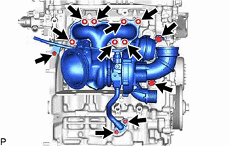
(b) Remove the inlet turbo oil pipe union bolt.
(c) Remove the 2 bolts and separate the No. 1 turbo water pipe sub-assembly.
(d) Remove the 7 nuts, collar and turbocharger sub-assembly from the cylinder head sub-assembly.
20. REMOVE EXHAUST MANIFOLD TO HEAD GASKET
Click here
21. REMOVE NO. 2 TURBO INSULATOR
|
(a) Remove the 2 bolts and No. 2 turbo insulator from the cylinder brock sub-assembly. |
|
22. REMOVE PURGE VALVE (PURGE VSV)
Click here
23. SEPARATE NO. 6 ENGINE WIRE
|
(a) Disengage the 5 clamps and separate the No. 6 engine wire. |
|
24. REMOVE NO. 2 ENGINE COVER BRACKET
|
(a) Remove the bolt and No. 2 engine cover bracket from the intake manifold. |
|
25. REMOVE INTAKE MANIFOLD
|
(a) Remove the 3 bolts and 2 nuts and intake manifold from the cylinder head sub-assembly. |
|

26. REMOVE NO. 1 VENTILATION FLANGE SEPARATOR
Click here
27. REMOVE NO. 1 INTAKE MANIFOLD TO HEAD GASKET
Click here
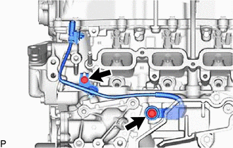
28. REMOVE WATER BY-PASS PIPE
|
(a) Remove the bolt and nut. |
|
(b) Slide the clip and remove the water by-pass pipe from the water inlet with thermostat sub-assembly.
29. REMOVE NO. 7 ENGINE WIRE
|
(a) Disengage the clamp. |
|

(b) Disconnect the connector and remove the No. 7 engine wire.
30. REMOVE FUEL TUBE SUB-ASSEMBLY
|
(a) Remove the fuel pipe clamp from the fuel tube connector. |
|
|
(b) Remove the bolt. |
|
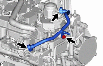
(c) Remove the fuel tube sub-assembly.
Click here
31. REMOVE OIL LEVEL GAGE SUB-ASSEMBLY
Click here
32. REMOVE OIL LEVEL GAGE GUIDE
Click here
33. REMOVE FUEL DELIVERY GUARD
Click here
34. REMOVE NO. 1 DELIVERY PIPE SPACER
(a) Remove the 2 No. 1 delivery pipe spacers.
35. REMOVE FUEL DELIVERY PIPE
Click here
36. REMOVE FUEL DELIVERY SPACER
Click here
37. REMOVE INJECTOR VIBRATION INSULATOR
Click here
38. REMOVE NO. 1 FUEL PIPE SUB-ASSEMBLY
Click here
39. REMOVE FUEL PUMP ASSEMBLY
Click here
40. REMOVE FUEL DELIVERY PIPE SUB-ASSEMBLY
Click here
41. REMOVE NO. 6 ENGINE WIRE
Click here
42. REMOVE DIRECT FUEL INJECTOR ASSEMBLY
Click here
43. REMOVE FUEL INJECTOR SEAL
Click here
44. REMOVE NO. 2 CYLINDER BLOCK INSULATOR
|
(a) Remove the No. 2 cylinder block insulator from the cylinder block sub-assembly. |
|
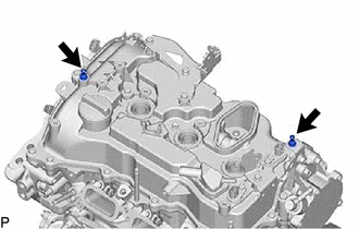
45. REMOVE SENSOR WIRE
|
(a) Remove the 2 bolts and remove the sensor wire from the cylinder block sub-assembly. |
|
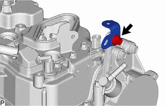
46. REMOVE VENTILATION HOSE
|
(a) Disengage the clamp. |
|
(b) Slide the clip and remove the ventilation hose from the cylinder head cover sub-assembly.
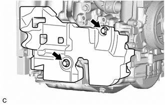
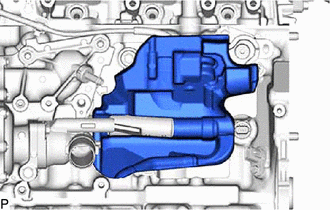
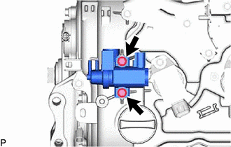
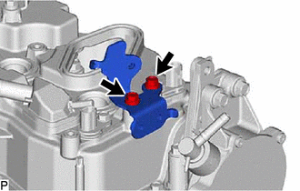
47. REMOVE VACUUM REGULATING VALVE ASSEMBLY
|
(a) Remove the 2 bolts and vacuum regulating valve assembly from the cylinder head cover sub-assembly. |
|
48. REMOVE IGNITION COIL ASSEMBLY
Click here
49. REMOVE ENGINE COVER JOINT
|
(a) Remove the 2 engine cover joints from the cylinder head cover sub-assembly. |
|
50. REMOVE ENGINE COVER BRACKET
|
(a) Remove the bolt and engine cover bracket from the No. 1 vacuum pump bracket. |
|
51. REMOVE FUEL HOSE BRACKET
|
(a) Remove the 2 bolts and fuel hose bracket form the cylinder head cover sub-assembly. |
|
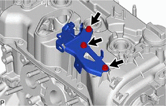
52. REMOVE INTAKE PIPE OR HOSE STAY
|
(a) Remove the 3 bolts and intake pipe or hose stay from the cylinder head cover sub-assembly. |
|
53. REMOVE NO. 3 CYLINDER BLOCK INSULATOR
|
(a) Remove the No. 3 cylinder block insulator from the cylinder block sub-assembly. |
|
|
|
|