| Last Modified: 05-13-2024 | 6.11:8.1.0 | Doc ID: RM1000000028KBN |
| Model Year Start: 2023 | Model: GR Corolla | Prod Date Range: [11/2022 - ] |
| Title: THEFT DETERRENT / KEYLESS ENTRY: THEFT DETERRENT SYSTEM: Engine Hood Courtesy Switch Circuit; 2023 - 2025 MY Corolla Corolla Hatchback Corolla HV GR Corolla [11/2022 - ] | ||
|
Engine Hood Courtesy Switch Circuit |
DESCRIPTION
The engine hood courtesy switch is built into the hood lock assembly. This switch turns on when the engine hood is closed and turns off when the engine hood is opened.
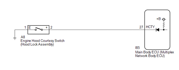
WIRING DIAGRAM
CAUTION / NOTICE / HINT
NOTICE:
Before replacing the main body ECU (multiplex network body ECU), refer to Registration.
for HV Model: Click here
![2023 - 2025 MY Corolla Corolla HV [09/2022 - ]; THEFT DETERRENT / KEYLESS ENTRY: SMART KEY SYSTEM (for Start Function, HV Model): REGISTRATION](/t3Portal/stylegraphics/info.gif)
for Gasoline Model: Click here
PROCEDURE
|
1. |
READ VALUE USING GTS |
(a) Read the Data List according to the display on the GTS.
Body Electrical > Main Body > Data List
|
Tester Display |
Measurement Item |
Range |
Normal Condition |
Diagnostic Note |
|---|---|---|---|---|
|
Hood Courtesy Switch Status |
Engine hood courtesy switch |
Close or Open |
Close: Engine hood closed Open: Engine hood open |
- |
OK:
The GTS display changes correctly in response to the Engine hood courtesy switch (hood lock assembly) status.
Body Electrical > Main Body > Data List
|
Tester Display |
|---|
|
Hood Courtesy Switch Status |
| OK |

|
|

|
2. |
INSPECT ENGINE HOOD COURTESY SWITCH (HOOD LOCK ASSEMBLY) |
Click here
| NG |
|
|
|
3. |
CHECK HARNESS AND CONNECTOR (ENGINE HOOD COURTESY SWITCH (HOOD LOCK ASSEMBLY) - MAIN BODY ECU (MULTIPLEX NETWORK BODY ECU) AND BODY GROUND)) |
(a) Disconnect the I85 main body ECU (multiplex network body ECU) connector.
(b) Measure the resistance according to the value(s) in the table below.
Standard Resistance:
|
Tester Connection |
Condition |
Specified Condition |
|---|---|---|
|
A8-2 (+) - I85-27 (HCTY) |
Always |
Below 1 Ω |
|
A8-2 (+) or I85-27 (HCTY) - Other terminals and body ground |
Always |
10 kΩ or higher |
|
A8-1 (E) - Body ground |
Always |
Below 1 Ω |
| OK |
|
| NG |
|
REPAIR OR REPLACE HARNESS OR CONNECTOR |
|
|
|