| Last Modified: 05-13-2024 | 6.11:8.1.0 | Doc ID: RM1000000028K97 |
| Model Year Start: 2023 | Model: GR Corolla | Prod Date Range: [11/2022 - ] |
| Title: THEFT DETERRENT / KEYLESS ENTRY: SMART KEY SYSTEM (for Entry Function): Back Door Entry Unlock Function does not Operate; 2023 - 2025 MY Corolla Corolla Hatchback Corolla HV GR Corolla [11/2022 - ] | ||
|
Back Door Entry Unlock Function does not Operate |
DESCRIPTION
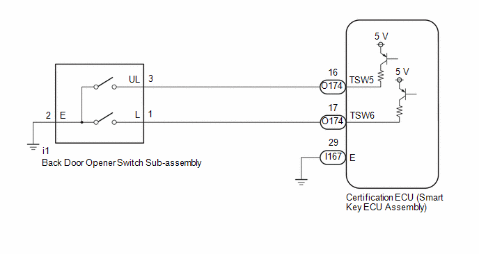
If the entry unlock function does not operate for the back door only, but the entry lock function operates, the request code is being transmitted properly from the back door. In this case, there may be a problem related to the open switch (connection between the back door opener switch sub-assembly and certification ECU (smart key ECU assembly)).
WIRING DIAGRAM

CAUTION / NOTICE / HINT
NOTICE:
-
When using the GTS with the ignition switch off, connect the GTS to the DLC3 and turn a courtesy light switch on and off at intervals of 1.5 seconds or less until communication between the GTS and the vehicle begins.
Then select Model Code "KEY REGIST" under manual mode and enter the following menus: Body Electrical / Smart Key(CAN). While using the GTS, periodically turn a courtesy light switch on and off at intervals of 1.5 seconds or less to maintain communication between the GTS and the vehicle.
- The smart key system (for Entry Function) uses the CAN communication system. Inspect the communication function by following How to Proceed with Troubleshooting. Troubleshoot the smart key system (for Entry Function) after confirming that the communication systems are functioning properly.
- Before replacing the certification ECU (smart key ECU assembly), refer to Precaution.
- Check that there are no electrical key transmitter sub-assemblies in the vehicle.
- After repair, confirm that no DTCs are output.
PROCEDURE
|
1. |
CHECK POWER DOOR LOCK CONTROL SYSTEM |
(a) When the door control switch on the multiplex network master switch assembly is operated, check that the back door lock and unlock according to the switch operation.
OK:
Back door lock/unlock operate normally.
| NG |

|
|
|
2. |
READ VALUE USING GTS (TRUNK LID/BACK DOOR UNLOCK SWITCH) |
(a) Read the Data List according to the display on the GTS.
Body Electrical > Smart Key > Data List
|
Tester Display |
Measurement Item |
Range |
Normal Condition |
Diagnostic Note |
|---|---|---|---|---|
|
Trunk Lid/Back Door Unlock Switch |
Back door opener switch sub-assembly (open switch) |
OFF or ON |
OFF: Back door opener switch sub-assembly (open switch) not pressed ON: Back door opener switch sub-assembly (open switch) pressed |
|
Body Electrical > Smart Key > Data List
|
Tester Display |
|---|
|
Trunk Lid/Back Door Unlock Switch |
OK:
The GTS display changes correctly in response to the operation of the back door opener switch sub-assembly.
| OK |

|
|
|
3. |
CHECK HARNESS AND CONNECTOR (BACK DOOR OPENER SWITCH SUB-ASSEMBLY - CERTIFICATION ECU (SMART KEY ECU ASSEMBLY)) |
(a) Disconnect the O174 certification ECU (smart key ECU assembly) connector.
(b) Disconnect the i1 back door opener switch sub-assembly connector.
(c) Measure the resistance according to the value(s) in the table below.
Standard Resistance:
|
Tester Connection |
Condition |
Specified Condition |
|---|---|---|
|
O174-16 (TSW5) - i1-3 (UL) |
Always |
Below 1 Ω |
|
O174-16 (TSW5) or i1-3 (UL) - Other terminals and body ground |
Always |
10 kΩ or higher |
| NG |

|
REPAIR OR REPLACE HARNESS OR CONNECTOR |
|
|
4. |
INSPECT BACK DOOR OPENER SWITCH SUB-ASSEMBLY (OPEN SWITCH) |
| OK |

|
| NG |

|
|
|
|
![2023 - 2025 MY Corolla Corolla Hatchback Corolla HV GR Corolla [11/2022 - ]; THEFT DETERRENT / KEYLESS ENTRY: SMART KEY SYSTEM (for Entry Function): HOW TO PROCEED WITH TROUBLESHOOTING](/t3Portal/stylegraphics/info.gif)
