| Last Modified: 05-13-2024 | 6.11:8.1.0 | Doc ID: RM1000000028JQB |
| Model Year Start: 2023 | Model: GR Corolla | Prod Date Range: [11/2022 - ] |
| Title: LIGHTING (EXT): LIGHTING SYSTEM: High Beam Headlight Circuit; 2023 - 2025 MY Corolla Corolla Hatchback Corolla HV GR Corolla [11/2022 - ] | ||
|
High Beam Headlight Circuit |
DESCRIPTION
The main body ECU (multiplex network body ECU) controls the high beam headlights.
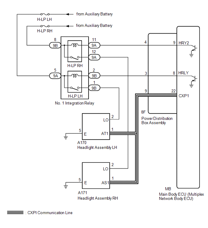
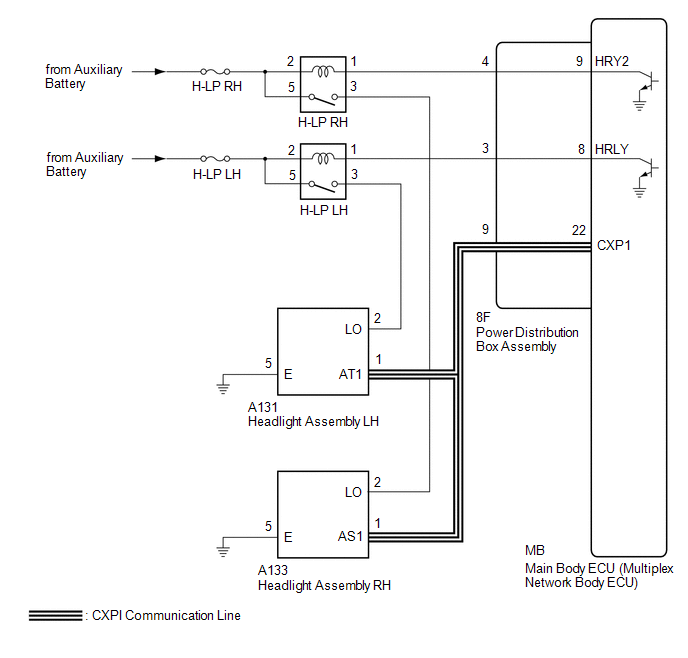
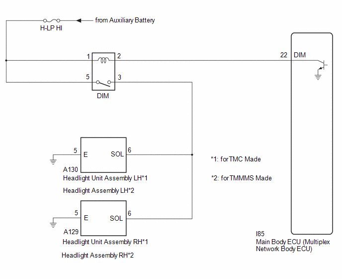
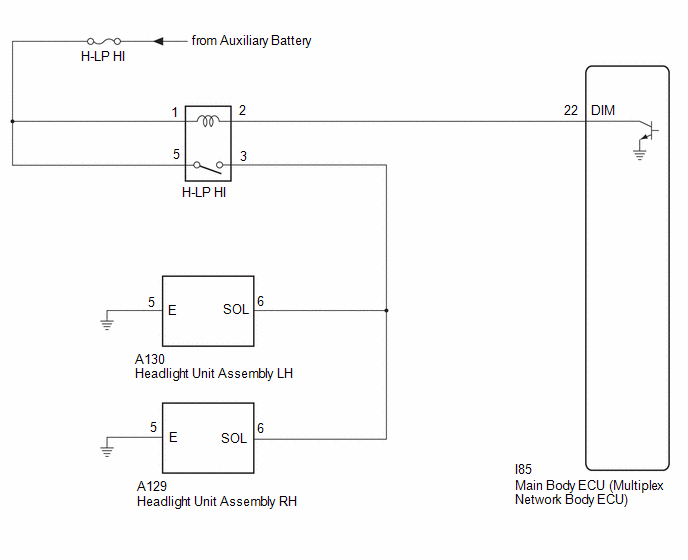
WIRING DIAGRAM
for LED Type Turn Signal Light (for G16E-GTS)
for LED Type Turn Signal Light (for M20A-FKS, 2ZR-FXE)
for Bulb Type Turn Signal Light (for M20A-FKS)
for Bulb Type Turn Signal Light (for 2ZR-FXE)
CAUTION / NOTICE / HINT
NOTICE:
- Inspect the fuses for circuits related to this system before performing the following procedure.
-
Before replacing the main body ECU (multiplex network body ECU), refer to Registration.
for HV Model:Click here
![2023 - 2025 MY Corolla Corolla HV [09/2022 - ]; THEFT DETERRENT / KEYLESS ENTRY: SMART KEY SYSTEM (for Start Function, HV Model): REGISTRATION](/t3Portal/stylegraphics/info.gif)
for Gasoline Model:Click here
-
First perform the communication function inspections in How to Proceed with Troubleshooting to confirm that there are no CXPI communication malfunctions before troubleshooting this symptom.
Click here
PROCEDURE
|
1. |
CONFIRM MODEL |
(a) Choose the model to be inspected.
|
Result |
Proceed to |
|---|---|
|
for LED Type Turn Signal Light |
A |
|
for Bulb Type Turn Signal Light |
B |
| B |

|
|

|
2. |
PERFORM ACTIVE TEST USING GTS |
(a) Perform the Active Test according to the display on the GTS.
Body Electrical > Main Body > Active Test
|
Tester Display |
Measurement Item |
Control Range |
Diagnostic Note |
|---|---|---|---|
|
High Beam Headlight |
High beam headlights |
OFF or ON |
- |
Body Electrical > Main Body > Active Test
|
Tester Display |
|---|
|
High Beam Headlight |
OK:
High beam headlights illuminate.
|
Result |
Proceed to |
|---|---|
|
OK |
A |
|
NG (LH side high beam headlight does not illuminate) |
B |
|
NG (RH side high beam headlight does not illuminate) |
C |
| A |
|
PROCEED TO NEXT SUSPECTED AREA SHOWN IN PROBLEM SYMPTOMS TABLE
|
| B |
|
| C |
|
|
3. |
PERFORM ACTIVE TEST USING GTS |
(a) Perform the Active Test according to the display on the GTS.
Body Electrical > Main Body > Active Test
|
Tester Display |
Measurement Item |
Control Range |
Diagnostic Note |
|---|---|---|---|
|
High Beam Headlight |
High beam headlights |
OFF or ON |
- |
Body Electrical > Main Body > Active Test
|
Tester Display |
|---|
|
High Beam Headlight |
OK:
High beam headlights illuminate.
| OK |
|
PROCEED TO NEXT SUSPECTED AREA SHOWN IN PROBLEM SYMPTOMS TABLE
|
|
|
4. |
CONFIRM MODEL |
(a) Choose the model to be inspected.
|
Result |
Proceed to |
|---|---|
|
for M20A-FKS |
A |
|
for 2ZR-FXE |
B |
| B |
|
|
|
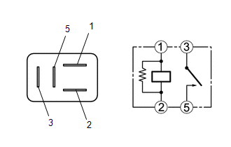
5. |
INSPECT DIM RELAY |
(a) Remove the DIM relay.
|
(b) Measure the resistance according to the value(s) in the table below. Standard Resistance:
|
|
| NG |
|
REPLACE DIM RELAY |
|
|
6. |
CHECK HARNESS AND CONNECTOR (POWER SOURCE - DIM RELAY) |
(a) Measure the voltage according to the value(s) in the table below.
Standard Voltage:
|
Tester Connection |
Condition |
Specified Condition |
|---|---|---|
|
1 (DIM relay) - Body ground |
Always |
11 to 14 V |
|
5 (DIM relay)- Body ground |
Always |
11 to 14 V |
| NG |
|
REPAIR OR REPLACE HARNESS OR CONNECTOR |
|
|
7. |
CHECK HARNESS AND CONNECTOR (DIM RELAY - MAIN BODY ECU (MULTIPLEX NETWORK BODY ECU)) |
(a) Disconnect the I85 main body ECU (multiplex network body ECU) connector.
(b) Measure the resistance according to the value(s) in the table below.
Standard Resistance:
|
Tester Connection |
Condition |
Specified Condition |
|---|---|---|
|
2 (DIM relay) - I85-22 (DIM) |
Always |
Below 1 Ω |
|
2 (DIM relay) or I85-22 (DIM) - Body ground |
Always |
10 kΩ or higher |
| OK |
|
| NG |
|
REPAIR OR REPLACE HARNESS OR CONNECTOR |
|
8. |
INSPECT H-LP HI RELAY |
(a) Remove the H-LP HI relay.
|
(b) Measure the resistance according to the value(s) in the table below. Standard Resistance:
|
|
| NG |
|
REPLACE H-LP HI RELAY |
|
|
9. |
CHECK HARNESS AND CONNECTOR (POWER SOURCE - H-LP HI RELAY) |
(a) Measure the voltage according to the value(s) in the table below.
Standard Voltage:
|
Tester Connection |
Condition |
Specified Condition |
|---|---|---|
|
1 (H-LP HI relay) - Body ground |
Always |
11 to 14 V |
|
5 (H-LP HI relay)- Body ground |
Always |
11 to 14 V |
| NG |
|
REPAIR OR REPLACE HARNESS OR CONNECTOR |
|
|
10. |
CHECK HARNESS AND CONNECTOR (DIM RELAY - MAIN BODY ECU (MULTIPLEX NETWORK BODY ECU)) |
(a) Disconnect the I85 main body ECU (multiplex network body ECU) connector.
(b) Measure the resistance according to the value(s) in the table below.
Standard Resistance:
|
Tester Connection |
Condition |
Specified Condition |
|---|---|---|
|
2 (H-LP HI relay) - I85-22 (DIM) |
Always |
Below 1 Ω |
|
2 (H-LP HI relay) or I85-22 (DIM) - Body ground |
Always |
10 kΩ or higher |
| OK |
|
| NG |
|
REPAIR OR REPLACE HARNESS OR CONNECTOR |
|
|
|