- Perform "Reset Memory"
- Perform "Calibration"
| Last Modified: 07-31-2024 | 6.11:8.1.0 | Doc ID: RM1000000028J5B |
| Model Year Start: 2023 | Model: Corolla Hatchback | Prod Date Range: [11/2022 - ] |
| Title: REAR SUSPENSION: REAR SUSPENSION MEMBER (for 2WD): REMOVAL; 2023 - 2025 MY Corolla Corolla Hatchback Corolla HV [11/2022 - ] | ||
REMOVAL
CAUTION / NOTICE / HINT
The necessary procedures (adjustment, calibration, initialization, or registration) that must be performed after parts are removed and installed, or replaced during rear suspension member sub-assembly removal/installation are shown below.
Necessary Procedures After Parts Removed/Installed/Replaced (for HV Model:)
|
Replaced Part or Performed Procedure |
Necessary Procedure |
Effect/Inoperative Function when Necessary Procedure not Performed |
Link |
|---|---|---|---|
|
Rear wheel alignment adjustment |
|
|
|
|
Gas leaks from exhaust system is repaired (2ZR-FXE) |
Inspection after repair |
|
Necessary Procedures After Parts Removed/Installed/Replaced (for Gasoline Model:)
|
Replaced Part or Performed Procedure |
Necessary Procedure |
Effect/Inoperative Function when Necessary Procedure not Performed |
Link |
|---|---|---|---|
|
Rear wheel alignment adjustment |
|
|
|
|
Gas leaks from exhaust system is repaired (M20A-FKS) |
Inspection after repair |
|
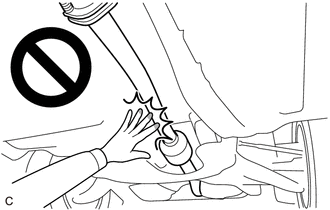
CAUTION:
To prevent burns, do not touch the engine, exhaust pipe or other high temperature components while the engine is hot.
PROCEDURE
1. REMOVE REAR WHEEL
2. REMOVE TAIL EXHAUST PIPE ASSEMBLY
3. REMOVE REAR FLOOR SIDE MEMBER COVER LH (w/ Cover)
4. REMOVE REAR FLOOR SIDE MEMBER COVER RH (w/ Cover)
5. SEPARATE REAR FLEXIBLE HOSE LH
(a) Remove the bolt and separate the rear flexible hose LH from the rear flexible hose bracket.
6. SEPARATE REAR FLEXIBLE HOSE RH
HINT:
Perform the same procedure as for the LH side.
7. REMOVE REAR STABILIZER LINK ASSEMBLY LH (for Hatchback)
8. REMOVE REAR STABILIZER LINK ASSEMBLY LH (for Sedan)
9. REMOVE REAR STABILIZER LINK ASSEMBLY RH (for Hatchback)
HINT:
Perform the same procedure as for the LH side.
10. REMOVE REAR STABILIZER LINK ASSEMBLY RH (for Sedan)
HINT:
Perform the same procedure as for the LH side.
11. REMOVE REAR STABILIZER BAR (for Hatchback)
12. REMOVE REAR STABILIZER BAR SUB-ASSEMBLY (for Sedan)
13. REMOVE REAR COIL SPRING LH
14. REMOVE REAR COIL SPRING RH
HINT:
Perform the same procedure as for the LH side.
15. REMOVE REAR LOWER COIL SPRING INSULATOR LH
16. REMOVE REAR LOWER COIL SPRING INSULATOR RH
HINT:
Perform the same procedure as for the LH side.
17. REMOVE REAR NO. 2 SUSPENSION ARM ASSEMBLY LH
18. REMOVE REAR NO. 2 SUSPENSION ARM ASSEMBLY RH
HINT:
Perform the same procedure as for the LH side.
19. REMOVE REAR NO. 1 SUSPENSION ARM ASSEMBLY LH
20. REMOVE REAR NO. 1 SUSPENSION ARM ASSEMBLY RH
HINT:
Perform the same procedure as for the LH side.
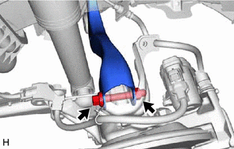
21. SEPARATE REAR UPPER CONTROL ARM ASSEMBLY LH
|
(a) Remove the bolt and nut and separate the rear upper control arm assembly LH from the rear axle carrier sub-assembly LH. NOTICE: Because the nut has its own stopper, do not turn the nut. Loosen the bolt with the nut secured. |
|
22. SEPARATE REAR UPPER CONTROL ARM ASSEMBLY RH
HINT:
Use the same procedure as for the LH side.
23. REMOVE REAR SUSPENSION MEMBER SUB-ASSEMBLY
(a) Using an engine lifter and 4 attachments or equivalent tools, support the rear suspension member sub-assembly as shown in the illustration.
CAUTION:
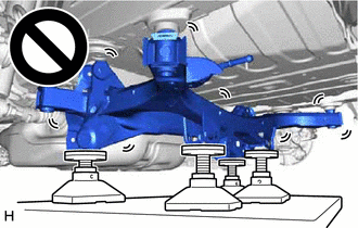
- The rear suspension member sub-assembly is a very heavy component. Make sure that it is supported securely.
- If the rear suspension member sub-assembly is not securely supported, it may drop, resulting in serious injury.
NOTICE:
Use attachments and wooden blocks to keep the rear suspension member sub-assembly level.
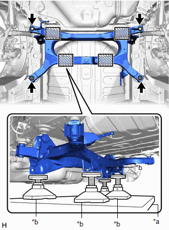
|
*a |
Engine Lifter |
|
*b |
Attachment |

|
Attachment Placement Location |
(b) Remove the 2 bolts and 2 nuts.
(c) Slowly lower the rear suspension member sub-assembly.
NOTICE:
When lowering the rear suspension member sub-assembly, be careful not to damage the vehicle body or other components installed to the vehicle.
24. REMOVE REAR UPPER CONTROL ARM ASSEMBLY LH
25. REMOVE REAR UPPER CONTROL ARM ASSEMBLY RH
HINT:
Perform the same procedure as for the LH side.
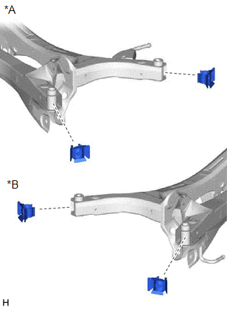
26. REMOVE REAR SUSPENSION MEMBER HOLE COVER (for TMMMS Made)
|
(a) Remove the 4 rear suspension member hole covers from the rear suspension member sub-assembly as shown in the illustration. |
|
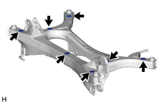
27. REMOVE HOLE PLUG (for TMMMS Made)
|
(a) Remove the 7 hole plugs from the rear suspension member sub-assembly as shown in the illustration. |
|
|
|
|
![2023 - 2025 MY Corolla Corolla HV [09/2022 - ]; BRAKE CONTROL / DYNAMIC CONTROL SYSTEMS: ELECTRONICALLY CONTROLLED BRAKE SYSTEM (for HV Model): UTILITY](/t3Portal/stylegraphics/info.gif)
