| Last Modified: 07-31-2024 | 6.11:8.1.0 | Doc ID: RM1000000028IY8 |
| Model Year Start: 2023 | Model: GR Corolla | Prod Date Range: [11/2022 - ] |
| Title: STEERING GEAR / LINKAGE: STEERING GEAR: INSTALLATION; 2023 - 2025 MY Corolla Corolla Hatchback Corolla HV GR Corolla [11/2022 - ] | ||
INSTALLATION
PROCEDURE
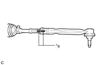
1. INSTALL TIE ROD END SUB-ASSEMBLY LH
|
(a) Install the lock nut and tie rod end sub-assembly LH to the steering gear assembly until the matchmarks are aligned. HINT: After adjusting the toe-in, tighten the lock nut. |
|
2. INSTALL TIE ROD END SUB-ASSEMBLY RH
HINT:
Perform the same procedure as for the LH side.
3. INSTALL STEERING LINK ASSEMBLY (except G16E-GTS)
(a) Install the steering link assembly to the front suspension crossmember sub-assembly with the 2 bolts and 2 new nuts.
Torque:
133 N·m {1356 kgf·cm, 98 ft·lbf}
NOTICE:
- Because the nut has its own stopper, do not turn the nut. Tighten the bolt with the nut secured.
- Make sure to tighten the bolts starting from the left side of the vehicle.
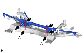
4. INSTALL STEERING LINK ASSEMBLY (for G16E-GTS)
|
(a) Install the steering link assembly, No. 2 steering rack housing bracket and No. 1 steering rack housing bracket to the front suspension crossmember sub-assembly with the 4 bolts and 2 new nuts. Torque: Bolt (A) : 133 N·m {1356 kgf·cm, 98 ft·lbf} Bolt (B) : 90 N·m {918 kgf·cm, 66 ft·lbf} NOTICE:
|
|
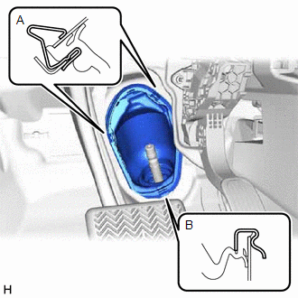
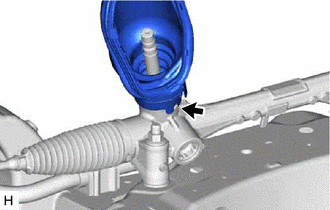
5. INSTALL NO. 1 STEERING COLUMN HOLE COVER SUB-ASSEMBLY
|
(a) Align the protrusion of the steering link assembly with the hole of the No. 1 steering column hole cover sub-assembly, and install the No. 1 steering column hole cover sub-assembly to the steering link assembly. HINT: Check that the No. 1 steering column hole cover sub-assembly is securely installed. |
|
6. INSTALL FRONT SUSPENSION CROSSMEMBER SUB-ASSEMBLY
7. CONNECT FRONT LOWER NO. 1 SUSPENSION ARM SUB-ASSEMBLY LH
8. CONNECT FRONT LOWER NO. 1 SUSPENSION ARM SUB-ASSEMBLY RH
HINT:
Perform the same procedure as for the LH side.
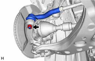
9. CONNECT TIE ROD END SUB-ASSEMBLY LH
|
(a) Connect the tie rod end sub-assembly LH to the steering knuckle LH with the nut. Torque: 49 N·m {500 kgf·cm, 36 ft·lbf} NOTICE:
|
|
(b) Install a new cotter pin.
10. CONNECT TIE ROD END SUB-ASSEMBLY RH
HINT:
Perform the same procedure as for the LH side.
11. CONNECT FRONT STABILIZER LINK ASSEMBLY LH
12. CONNECT FRONT STABILIZER LINK ASSEMBLY RH
HINT:
Perform the same procedure as for the LH side.
13. INSTALL REAR SIDE RAIL REINFORCEMENT SUB-ASSEMBLY LH
14. INSTALL REAR SIDE RAIL REINFORCEMENT SUB-ASSEMBLY RH (except G16E-GTS)
HINT:
Perform the same procedure as for the LH side.
15. INSTALL REAR SIDE RAIL REINFORCEMENT SUB-ASSEMBLY RH (for G16E-GTS)
16. INSTALL NO. 2 ENGINE UNDER COVER AIR GUIDE (for G16E-GTS with Engine Under Cover Air Guide)
17. INSTALL WINDSHIELD WASHER JAR ASSEMBLY (for G16E-GTS with Engine Under Cover Air Guide)
18. INSTALL INLET HOSE (for G16E-GTS with Engine Under Cover Air Guide)
19. INSTALL FRONT BUMPER ASSEMBLY (for G16E-GTS with Engine Under Cover Air Guide)
20. INSTALL FRONT FENDER LINER RH (for G16E-GTS with Engine Under Cover Air Guide)
21. ADD WASHER FLUID (for G16E-GTS with Engine Under Cover Air Guide)
22. INSTALL REAR ENGINE UNDER COVER LH (for G16E-GTS)
23. INSTALL REAR ENGINE UNDER COVER LH (except G16E-GTS)
24. INSTALL REAR ENGINE UNDER COVER RH
25. INSTALL NO. 1 ENGINE UNDER COVER ASSEMBLY
26. CONNECT NO. 1 STEERING COLUMN HOLE COVER SUB-ASSEMBLY
|
(a) Engage the clip (B) to the vehicle body. |
|
(b) Engage the clip (A) to install the No. 1 steering column hole cover sub-assembly to the vehicle body.
NOTICE:
- Be careful not to damage the lip of the No. 1 steering column hole cover sub-assembly.
- Check that the No. 1 steering column hole cover sub-assembly is securely installed.
- Check that the No. 1 steering column hole cover sub-assembly and vehicle body are in close contact with one another.
27. CONNECT NO. 2 STEERING INTERMEDIATE SHAFT ASSEMBLY
28. INSTALL COLUMN HOLE COVER SILENCER SHEET
29. INSTALL FRONT WHEELS
30. INSPECT AND ADJUST FRONT WHEEL ALIGNMENT
31. PERFORM END POSITION INITIAL SETTING (for HV Model)
32. PERFORM END POSITION INITIAL SETTING (for Gasoline Model)
|
|
|
![2023 - 2025 MY Corolla Corolla Hatchback Corolla HV GR Corolla [11/2022 - ]; FRONT SUSPENSION: FRONT SUSPENSION MEMBER: INSTALLATION+](/t3Portal/stylegraphics/info.gif)
