- Back door opener
| Last Modified: 01-27-2025 | 6.11:8.1.0 | Doc ID: RM1000000028IQI |
| Model Year Start: 2023 | Model: GR Corolla | Prod Date Range: [11/2022 - ] |
| Title: G16E-GTS (FUEL): FUEL SENDER GAUGE ASSEMBLY: REMOVAL; 2023 - 2025 MY GR Corolla [11/2022 - ] | ||
REMOVAL
CAUTION / NOTICE / HINT
The necessary procedures (adjustment, calibration, initialization or registration) that must be performed after parts are removed and installed, or replaced during fuel sender gauge assembly removal/installation are shown below.
CAUTION:
-
Never perform work on fuel system components near any possible ignition sources.
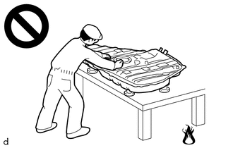
- Vaporized fuel could ignite, resulting in a serious accident.
-
Do not perform work on fuel system components without first disconnecting the cable from the negative (-) battery terminal.
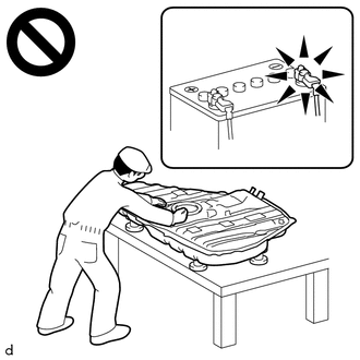
- Sparks could cause vaporized fuel to ignite, resulting in a serious accident.
HINT:
When the cable is disconnected / reconnected to the battery terminal, systems temporarily stop operating. However, each system has a function that completes learning the first time the system is used.
Learning completes when vehicle is driven
|
Effect/Inoperative Function when Necessary Procedure not Performed |
Necessary Procedure |
Link |
|---|---|---|
|
Front Camera System |
Drive the vehicle straight ahead at 35 km/h (22 mph) or more for 5 seconds or more. |
|
Learning completes when vehicle is operated normally
|
Effect/Inoperative Function when Necessary Procedure not Performed |
Necessary Procedure |
Link |
|---|---|---|
|
Power Door Lock Control System |
Perform door unlock operation with door control switch or electrical key transmitter sub-assembly switch. |
|
PROCEDURE
1. REMOVE FUEL SUCTION TUBE WITH PUMP AND GAUGE ASSEMBLY
Click here
![2023 - 2025 MY GR Corolla [11/2022 - ]; G16E-GTS (FUEL): FUEL PUMP: REMOVAL](/t3Portal/stylegraphics/info.gif)
2. REMOVE FUEL SENDER GAUGE ASSEMBLY
|
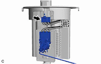
(a) Disconnect the fuel sender gauge assembly connector. |
|
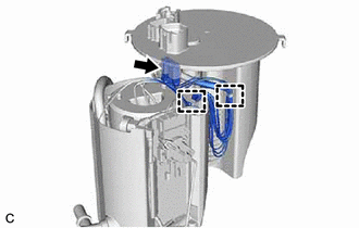
(b) Disengage the 2 clamps to disconnect the wire harness from the fuel suction plate sub-assembly.
NOTICE:
- Do not damage the wire harness.
- When disengaging each wire harness from the clamp, disengage one wire at a time.
|
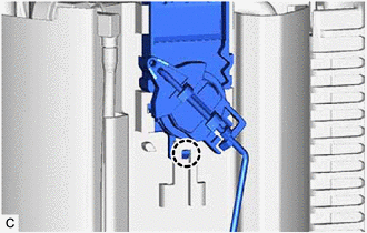
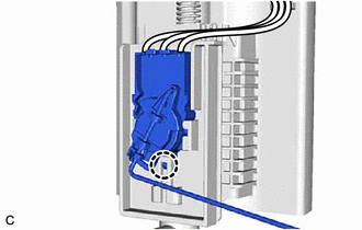
(c) Disengage the claw to remove the fuel sender gauge assembly from the fuel sub-tank. NOTICE: Be careful not to bend the arm of the fuel sender gauge assembly. |
|
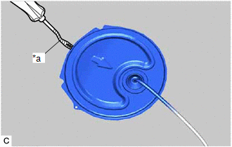
3. REMOVE REAR FLOOR SERVICE HOLE COVER (for RH Side)
|
(a) Using a clip remover with its tip wrapped with protective tape, remove the rear floor service hole cover and butyl tape. |
|
|
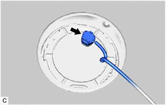
(b) Disconnect the fuel tank vent tube assembly connector. |
|
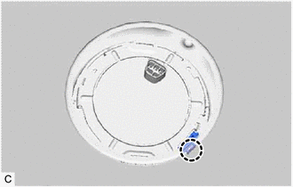
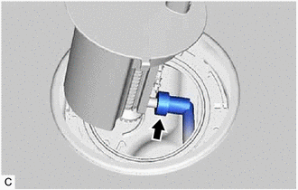
4. REMOVE NO. 1 FUEL TUBE CLAMP
|
(a) Disengage the claw to remove the No. 1 fuel tube clamp from the fuel pump gauge retainer. |
|
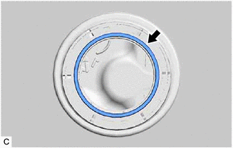
5. REMOVE FUEL PUMP GAUGE RETAINER (for RH Side)
HINT:
Perform the same procedure as for the fuel suction tube with pump and gauge assembly.
Click here
6. REMOVE FUEL TANK VENT TUBE ASSEMBLY
|
(a) Disconnect the fuel return vent tube sub-assembly and remove the fuel tank vent tube assembly from the fuel tank sub-assembly. Click here
NOTICE:
|
|
|
(b) Remove the fuel suction tube set gasket from the fuel tank sub-assembly. |
|
7. REMOVE NO. 2 FUEL SENDER GAUGE ASSEMBLY
|
(a) Disconnect the No. 2 fuel sender gauge assembly connector. |
|
(b) Disengage the clamp to disconnect the wire harness from the fuel tank vent tube assembly.
NOTICE:
- Do not damage the wire harness.
- When disengaging each wire harness from the clamp, disengage one wire at a time.
|
(c) Disengage the claw to remove the No. 2 fuel sender gauge assembly from the fuel tank vent tube assembly. NOTICE: Be careful not to bend the arm of the No. 2 fuel sender gauge assembly. |
|
|
|
|