- Replacement of throttle body with motor assembly
- Cleaning the deposits from the throttle body with motor assembly
| Last Modified: 05-13-2024 | 6.11:8.1.0 | Doc ID: RM1000000028GQI |
| Model Year Start: 2023 | Model: GR Corolla | Prod Date Range: [11/2022 - ] |
| Title: G16E-GTS (COOLING): THERMOSTAT: REMOVAL; 2023 - 2025 MY GR Corolla [11/2022 - ] | ||
REMOVAL
CAUTION / NOTICE / HINT
The necessary procedures (adjustment, calibration, initialization or registration) that must be performed after parts are removed and installed, or replaced during water inlet with thermostat sub-assembly removal/installation are shown below.
Necessary Procedures After Parts Removed/Installed/Replaced
|
Replaced Part or Performed Procedure |
Necessary Procedure |
Effect/Inoperative Function when Necessary Procedure not Performed |
Link |
|---|---|---|---|
|
|
Inspection After Repair |
|
NOTICE:
This procedure includes the removal of small-head bolts. Refer to Small-Head Bolts of Basic Repair Hint to identify the small-head bolts.
HINT:
When the cable is disconnected / reconnected to the battery terminal, systems temporarily stop operating. However, each system has a function that completes learning the first time the system is used.
Learning completes when vehicle is driven
|
Effect/Inoperative Function when Necessary Procedure not Performed |
Necessary Procedure |
Link |
|---|---|---|
|
*1: for GR Model
*2: except GR Model |
||
|
Front Camera System |
|
|
Learning completes when vehicle is operated normally
|
Effect/Inoperative Function when Necessary Procedure not Performed |
Necessary Procedure |
Link |
|---|---|---|
|
Power Door Lock Control System
|
Perform door unlock operation with door control switch or electrical key transmitter sub-assembly switch. |
PROCEDURE
1. REMOVE NO. 1 ENGINE UNDER COVER ASSEMBLY
2. DRAIN ENGINE COOLANT
3. REMOVE INTAKE MANIFOLD
4. REMOVE GENERATOR ASSEMBLY
5. DISCONNECT NO. 5 WATER BY-PASS HOSE
|
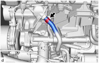
(a) Slide the clip and disconnect the No. 5 water by-pass hose from the water inlet with water pump housing sub-assembly. |
|
6. DISCONNECT NO. 2 RADIATOR HOSE
|
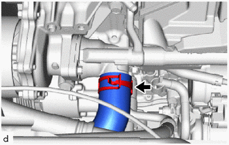
(a) Slide the clip and disconnect the No. 2 radiator hose from the water inlet with thermostat sub-assembly. |
|
7. REMOVE AIR CONNECTOR STAY
|
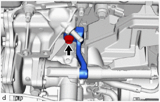
(a) Remove the bolt and air connector stay from the water inlet with water pump housing sub-assembly. |
|
8. REMOVE WATER INLET WITH WATER PUMP HOUSING SUB-ASSEMBLY
|
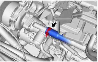
(a) Slide the clip and disconnect the No. 4 water by-pass hose from the water inlet with thermostat sub-assembly. NOTICE:
|
|
|
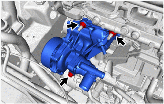
(b) Remove the bolt, 2 nuts and water inlet with water pump housing sub-assembly from the cylinder block sub-assembly. |
|
|
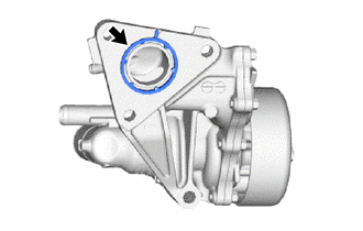
(c) Remove the gasket from the water inlet with water pump housing sub-assembly. |
|
9. REMOVE WATER INLET WITH THERMOSTAT SUB-ASSEMBLY
|
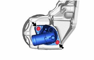
(a) Remove the 2 bolts and water inlet with thermostat sub-assembly. |
|
|
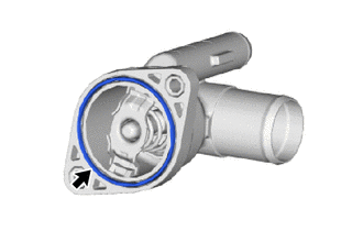
(b) Remove the gasket from the water inlet with thermostat sub-assembly. |
|
|
|
|
![2023 - 2025 MY GR Corolla [09/2022 - ]; G16E-GTS (ENGINE CONTROL): SFI SYSTEM: INITIALIZATION](/t3Portal/stylegraphics/info.gif)
