| Last Modified: 07-31-2024 | 6.11:8.1.0 | Doc ID: RM1000000028FYU |
| Model Year Start: 2023 | Model: GR Corolla | Prod Date Range: [11/2022 - ] |
| Title: SUPPLEMENTAL RESTRAINT SYSTEMS: CENTER AIRBAG SENSOR ASSEMBLY: INSTALLATION; 2023 - 2025 MY Corolla Corolla Hatchback Corolla HV GR Corolla [11/2022 - ] | ||
INSTALLATION
CAUTION / NOTICE / HINT
NOTICE:
- After replacing the airbag sensor assembly, make sure to perform ECU Configuration, Update ECU Security Key, Write VIN/Vehicle Identification Number, and Switching Specification Information.
- After performing the ECU configuration procedure and update ECU security key procedure, make sure to perform the initialization procedure for when the cable has been disconnected and reconnected to the negative (-) auxiliary battery terminal.
PROCEDURE
1. INSTALL AIRBAG SENSOR ASSEMBLY
(a) Check that the ignition switch (for Gasoline Model) or power switch (for HV Model) is off.
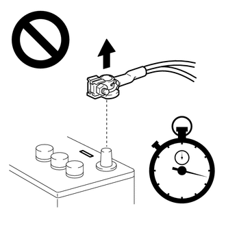
(b) Check that the cable is disconnected from the negative (-) auxiliary battery terminal.
CAUTION:
Wait at least 60 seconds after disconnecting the cable from the negative (-) auxiliary battery terminal to disable the SRS system.

|
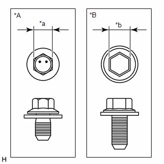
(c) Make sure to check the type of bolt before installation as it will vary depending on the case type of the airbag sensor assembly. |
|
|
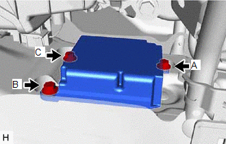
(d) Install the airbag sensor assembly with the 3 bolts. Torque: 17.5 N·m {178 kgf·cm, 13 ft·lbf} NOTICE:
|
|
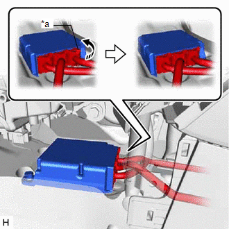
(e) Temporarily connect the connector and then move the lock lever in the direction indicated by the arrow to securely connect the connectors.
NOTICE:
When connecting any airbag connector, take care not to damage the airbag wire harness.

|
*a |
Lock Lever |

|
Move in this Direction |
(f) Check that there is no looseness in the installed parts of the airbag sensor assembly.
2. INSTALL FRONT NO. 1 CONSOLE BOX INSERT
3. INSTALL NO. 1 INSTRUMENT PANEL UNDER COVER SUB-ASSEMBLY
4. CONNECT CABLE TO NEGATIVE AUXILIARY BATTERY TERMINAL
5. ECU CONFIGURATION
6. UPDATE ECU SECURITY KEY
7. WRITE VIN/VEHICLE IDENTIFICATION NUMBER
8. SWITCHING SPECIFICATION INFORMATION
9. INSTALL DECK BOARD ASSEMBLY (for G16E-GTS)
10. INSPECT SRS WARNING LIGHT
11. INITIALIZATION AFTER RECONNECTING AUXILIARY BATTERY TERMINAL
HINT:
When disconnecting and reconnecting the battery, there is an automatic learning function that completes learning when the respective system is used.
12. PERFORM INITIALIZATION
for Electronically Controlled Brake System (for Gasoline Model with Electric Parking Brake System): Click here
![2023 - 2025 MY Corolla Corolla Hatchback GR Corolla [11/2022 - ]; BRAKE CONTROL / DYNAMIC CONTROL SYSTEMS: ELECTRONICALLY CONTROLLED BRAKE SYSTEM (for Gasoline Model with Electric Parking Brake System): UTILITY](/t3Portal/stylegraphics/info.gif)
for Electronically Controlled Brake System (for Gasoline Model without Electric Parking Brake System): Click here
![2023 - 2025 MY Corolla Corolla Hatchback GR Corolla [09/2022 - ]; BRAKE CONTROL / DYNAMIC CONTROL SYSTEMS: ELECTRONICALLY CONTROLLED BRAKE SYSTEM (for Gasoline Model without Electric Parking Brake System TMC Made): UTILITY](/t3Portal/stylegraphics/info.gif)
for Electronically Controlled Brake System (for HV Model): Click here
![2023 - 2025 MY Corolla Corolla HV [09/2022 - ]; BRAKE CONTROL / DYNAMIC CONTROL SYSTEMS: ELECTRONICALLY CONTROLLED BRAKE SYSTEM (for HV Model): UTILITY](/t3Portal/stylegraphics/info.gif)
for Active Torque Split AWD System: Click here
![2023 - 2025 MY Corolla Corolla Hatchback GR Corolla [09/2022 - ]; GF1A (TRANSFER / 4WD / AWD): ACTIVE TORQUE SPLIT AWD SYSTEM: CALIBRATION](/t3Portal/stylegraphics/info.gif)
for Occupant Classification System (for TMC Made): Click here
![2023 - 2025 MY Corolla Corolla Hatchback Corolla HV GR Corolla [09/2022 - ]; SUPPLEMENTAL RESTRAINT SYSTEMS: OCCUPANT CLASSIFICATION SYSTEM (for TMC Made): INITIALIZATION](/t3Portal/stylegraphics/info.gif)
for Occupant Classification System (for TMMMS Made): Click here
![2023 - 2025 MY Corolla Corolla Hatchback Corolla HV GR Corolla [11/2022 - ]; SUPPLEMENTAL RESTRAINT SYSTEMS: OCCUPANT CLASSIFICATION SYSTEM (for TMMMS Made): INITIALIZATION](/t3Portal/stylegraphics/info.gif)
|
|
|

