| Last Modified: 01-27-2025 | 6.11:8.1.0 | Doc ID: RM1000000028FMF |
| Model Year Start: 2023 | Model: GR Corolla | Prod Date Range: [11/2022 - 08/2023] |
| Title: EXTERIOR PANELS / TRIM: FRONT BUMPER (for Hatchback, GR): REASSEMBLY; 2023 MY Corolla Corolla Hatchback Corolla HV GR Corolla [11/2022 - 08/2023] | ||
REASSEMBLY
PROCEDURE
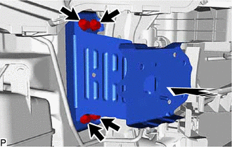
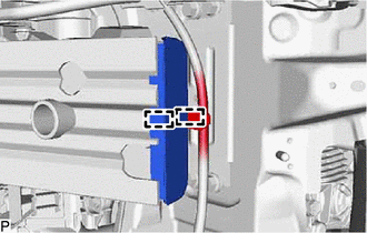
1. INSTALL FRONT BUMPER BRACKET LH
(a) Install the front bumper bracket LH with the 4 bolts as shown in the illustration.

|
Install in this Direction |
Torque:
16 N·m {163 kgf·cm, 12 ft·lbf}
2. INSTALL FRONT BUMPER BRACKET RH
HINT:
Use the same procedure as for the LH side.
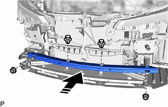
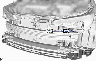
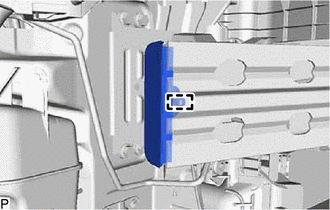
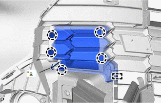
3. INSTALL NO. 2 FRONT BUMPER REINFORCEMENT
(a) Install the No. 2 front bumper reinforcement with the 2 nuts as shown in the illustration.
|
|
Install in this Direction |
Torque:
32 N·m {326 kgf·cm, 24 ft·lbf}
(b) w/ Engine Under Cover Air Guide Bracket:
(1) Install the 2 clips.
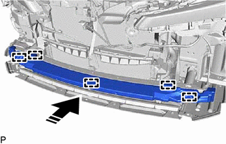
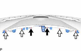
4. INSTALL LOWER FRONT BUMPER ABSORBER
(a) Engage the 5 guides as shown in the illustration to install the lower front bumper absorber.
|
|
Install in this Direction |
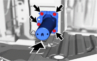
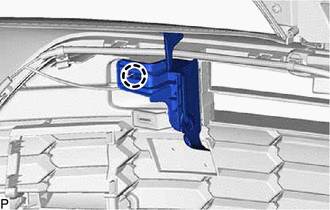
5. INSTALL FRONT SIDE MEMBER BRACKET SUB-ASSEMBLY RH
(a) Install the front side member bracket sub-assembly RH with the 4 bolts as shown in the illustration.
|
|
Install in this Direction |
Torque:
67 N·m {683 kgf·cm, 49 ft·lbf}
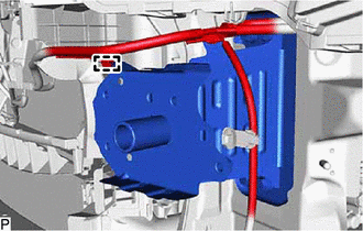
6. INSTALL FRONT SIDE MEMBER BRACKET SUB-ASSEMBLY LH
(a) Install the front side member bracket sub-assembly LH with the 4 bolts as shown in the illustration.

|
|
Install in this Direction |
Torque:
67 N·m {683 kgf·cm, 49 ft·lbf}
|
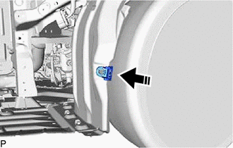
(b) Engage the clamp. |
|
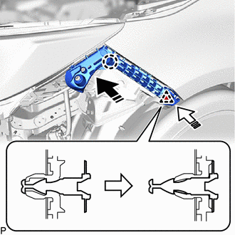
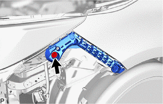
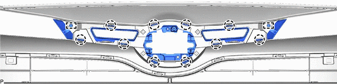
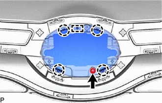
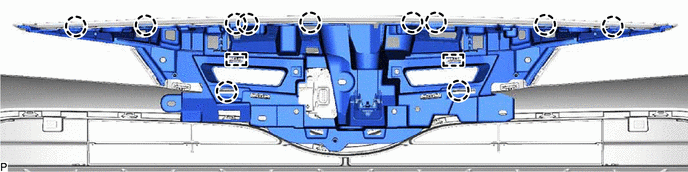
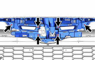
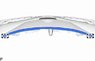
7. INSTALL FRONT BUMPER REINFORCEMENT SUB-ASSEMBLY
(a) Engage the guide as shown in the illustration.
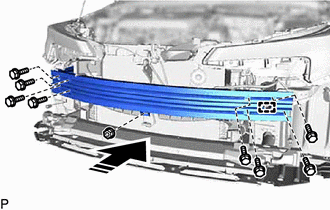
|
|
Install in this Direction |
(b) Install the front bumper reinforcement with the 8 bolts and nut.
Torque:
Bolt :
67 N·m {683 kgf·cm, 49 ft·lbf}
Nut :
8.4 N·m {86 kgf·cm, 74 in·lbf}
|
(c) Engage each clamp. |
|
8. INSTALL FRONT RADIATOR SIDE AIR GUIDE PLATE
(a) for LH side:
|
(1) Install the front radiator side air guide plate. |
|
(2) Engage the 2 clamps.
(b) for RH side:
|
(1) Engage the clamp to install the front radiator side air guide plate. |
|
9. INSTALL FRONT BUMPER ENERGY ABSORBER
Click here
![2023 - 2025 MY Corolla Corolla Hatchback Corolla HV GR Corolla [09/2022 - ]; EXTERIOR PANELS / TRIM: FRONT BUMPER (for Hatchback except GR): REASSEMBLY+](/t3Portal/stylegraphics/info.gif)
10. INSTALL NO. 2 LOWER FRONT BUMPER RETAINER
Click here
11. INSTALL FRONT BUMPER SIDE SUPPORT LH
(a) Engage the claw as shown in the illustration.
|
|
Install in this Direction |
(b) Engage the clip as shown in the illustration.
|
(c) Install the front bumper side support LH with the bolt. Torque: 8.0 N·m {82 kgf·cm, 71 in·lbf} |
|
12. INSTALL FRONT BUMPER SIDE SUPPORT RH
HINT:
Use the same procedure as for the LH side.
13. INSTALL FRONT FENDER LINER RETAINER
(a) Install the front fender liner retainer as shown in the illustration.
|
|
Install in this Direction |
HINT:
Use the same procedure for the RH side and LH side.
14. INSTALL PIN HOLD CLIP
(a) Engage the 2 claws as shown in the illustration to install the pin hold clip.
HINT:
Use the same procedure for the RH side and LH side.
|
|
Install in this Direction |
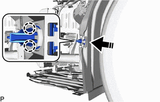
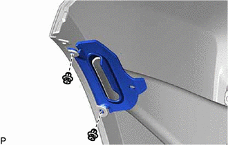
15. INSTALL FRONT BUMPER HOLE COVER LH
|
(a) Engage the 4 claws. |
|
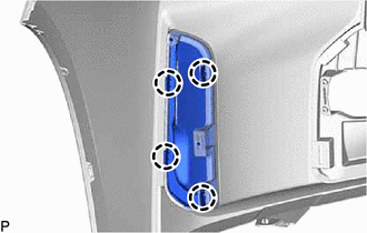
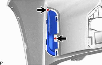
|
(b) Install the front bumper hole cover LH with the 2 screws. |
|
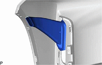
16. INSTALL FRONT BUMPER HOLE COVER RH
HINT:
Use the same procedure as for the LH side.
17. INSTALL AIR INTAKE DUCT LH
|
(a) Install the air intake duct LH. |
|
18. INSTALL AIR INTAKE DUCT RH
HINT:
Use the same procedure as for the LH side.
19. INSTALL COOL AIR INTAKE DUCT LH
|
(a) Install the cool air intake duct LH with the 2 clips. |
|
20. INSTALL COOL AIR INTAKE DUCT RH
HINT:
Use the same procedure as for the LH side.
21. INSTALL LOWER RADIATOR GRILLE SUB-ASSEMBLY
(a) Engage the 2 guides and 19 claws to install the radiator grille sub-assembly.
(b) Install the lower radiator grille sub-assembly with the 4 clips.
22. INSTALL AIR INTAKE DUCT LH (w/ Engine Under Cover Air Guide Bracket)
(a) Temporarily install the air intake duct LH to the No. 2 intercooler air guide.
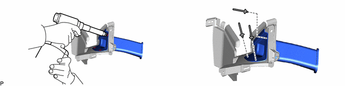
(b) Using an air riveter or hand riveter with a nose piece, install the air intake duct LH with 3 new rivets.
HINT:
If the mandrel of the rivet does not come off on the first operation of the rivet gun, slide the rivet gun forward on the mandrel and operate it again.
NOTICE:
-
Do not pry the rivet with the riveter, as this will cause damage to the riveter and mandrel.
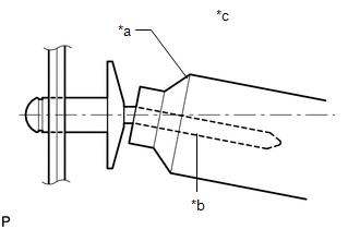
*a
Riveter
*b
Mandrel
*c
Incorrect
-
Confirm that the rivets are seated properly against the moulding.
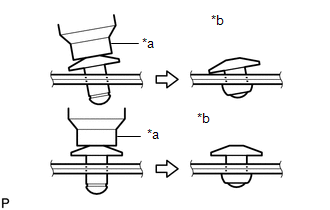
*a
Riveter
*b
Incorrect
- Do not tilt the riveter when installing the rivet to the moulding.
- Do not leave any space between the rivet head and moulding.
-
Do not leave any space between the moulding and door frame. Firmly hold the 2 items together while installing the rivet.
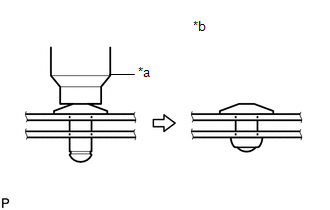
*a
Riveter
*b
Incorrect
23. INSTALL AIR INTAKE DUCT RH (w/ Engine Under Cover Air Guide Bracket)
HINT:
Use the same procedure as for the LH side.
24. INSTALL NO. 2 INTERCOOLER AIR GUIDE
|
(a) Engage the 2 claws. |
|
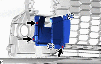
(b) Install the No. 2 intercooler air guide with the 3 screws.
25. INSTALL NO. 1 INTERCOOLER AIR GUIDE
HINT:
Use the same procedure as for the LH side.
26. INSTALL RADIATOR GRILLE LOWER SIDE LH
|
(a) Engage the hook. |
|
(b) Engage the guide and 5 claws to install the lower side radiator grille LH.
27. INSTALL RADIATOR GRILLE
(a) Engage the 2 guides and 10 claws to install the radiator grille.
28. INSTALL RADIATOR GRILLE (OR FRONT PANEL) EMBLEM
|
(a) Engage the guide and 4 claws. |
|
(b) Install the radiator grille (or front panel) emblem with the screw.
29. INSTALL MILLIMETER WAVE RADAR SENSOR ASSEMBLY
Click here
30. INSTALL HOOD TO FRONT END PANEL SEAL
Click here
31. INSTALL INNER RADIATOR GRILLE
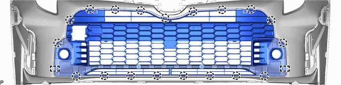
(a) Engage the 2 guides and 11 claws.
|
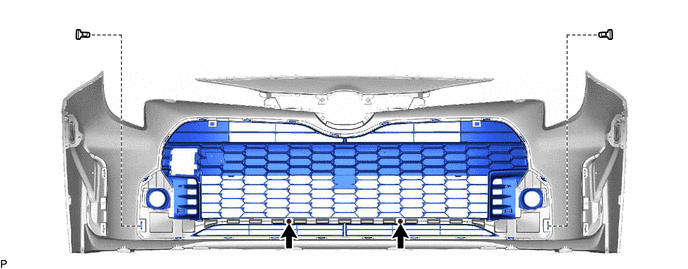
(b) Install the 6 screws. |
|
(c) Install the 4 clips and 2 screws.

|
Screw |

|
Clip |
|
(d) Engage the 2 guides to install the inner radiator grille. |
|
32. INSTALL NO. 3 RADIATOR TO SUPPORT SEAL
|
(a) Engage the claw to install the No. 3 radiator to support seal. |
|
33. INSTALL NO. 2 RADIATOR TO SUPPORT SEAL
HINT:
Use the same procedure as for the LH side.
34. INSTALL RADIATOR GRILLE EMBLEM ASSEMBLY
HINT:
When installing the radiator grille emblem assembly, heat the rear radiator grille sub-assembly using a heat light.
Heating Temperature:
|
Item |
Temperature |
|---|---|
|
Radiator Grille Sub-assembly |
20 to 30 °C (68 to 86 °F) |
CAUTION:
- Do not touch the heat light and heated parts, touching the heat light may result in burns.
- Touching heated parts for a long time may result in burns.
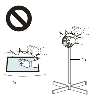
|
*a |
Heated Part |
|
*b |
Heat Light |
NOTICE:
Do not heat the radiator grille sub-assembly excessively.
(a) Clean the radiator grille sub-assembly.
(1) Using a heat light, heat the radiator grille sub-assembly surface.
(2) Remove any remaining double-sided tape from the radiator grille sub-assembly.
(3) Wipe off any tape adhesive residue with cleaner.
(b) Using a heat light, heat the radiator grille sub-assembly and a new radiator grille emblem assembly.
(c) Remove the release paper from the radiator grille emblem assembly.
HINT:
After removing the release paper, keep the exposed adhesive free from foreign matter.
|
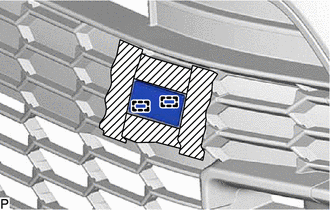
(d) Engage the 2 pins and install the radiator grille emblem assembly as shown in the illustration. |
|
35. INSTALL FOG LIGHT ASSEMBLY LH
Click here
36. INSTALL FOG LIGHT ASSEMBLY RH
HINT:
Use the same procedure as for the LH side.
|
|
|