- Engine switch on (IG)
- Shift lever in M
| Last Modified: 05-13-2024 | 6.11:8.1.0 | Doc ID: RM1000000028EKV |
| Model Year Start: 2023 | Model: Corolla Hatchback | Prod Date Range: [11/2022 - ] |
| Title: K120 / K121 (CVT): K120 CONTINUOUSLY VARIABLE TRANSAXLE SYSTEM: TERMINALS OF ECU; 2023 - 2025 MY Corolla Corolla Hatchback [11/2022 - ] | ||
TERMINALS OF ECU
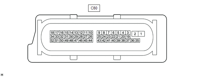
TCM
HINT:
The standard voltage and resistance between each pair of TCM terminals is shown in the table below.
The appropriate conditions for checking each pair of terminals are also indicated. The result of checks should be compared with the standard voltage or resistance for that pair of terminals shown in the "Specified Condition" column.
Use the illustration above as a reference for the TCM terminals.
|
Terminal No. (Symbol) |
Wiring Color |
Terminal Description |
Condition |
Specified Condition |
|---|---|---|---|---|
|
*1: w/ Sequential Shift
*2: w/o Sequential Shift |
||||
|
C80-1 (+B) - C80-2 (E1) |
R - W-B |
Power source of TCM |
Engine switch on (IG) |
11 to 14 V |
|
C80-2 (E1) - Body ground |
W-B - Body ground |
Ground |
Always |
Below 1 Ω |
|
C80-4 (SLS+) - C80-3 (SLS-) |
B - L |
Shift solenoid valve SLS signal |
Engine idling |
Pulse generation |
|
C80-6 (SLU+) - C80-5 (SLU-) |
G - GR |
Shift solenoid valve SLU signal |
Lock-up turned from OFF to ON |
Pulse generation |
|
C80-7 (NSSO) - C80-2 (E1) |
R - W-B |
Transmission revolution sensor (NSS) signal |
Vehicle being driven with shift lever in D |
Pulse generation |
|
C80-8 (NC1O) - C80-2 (E1) |
V - W-B |
Transmission revolution sensor (NC1) signal |
Vehicle being driven in gear mode |
Pulse generation |
|
C80-9 (NTO) - C80-2 (E1) |
L - W-B |
Transmission revolution sensor (NT) signal |
Vehicle being driven with shift lever in D |
Pulse generation |
|
C80-10 (NOO) - C80-2 (E1) |
GR - W-B |
Transmission revolution sensor (NOUT) signal |
Vehicle being driven with shift lever in D |
Pulse generation |
|
C80-13 (NE) - C80-2 (E1) |
B - W-B |
Crankshaft position sensor signal from ECM |
Engine idling with warm engine |
Pulse generation |
|
C80-14 (S) - C80-2 (E1)*1 |
B - W-B |
M position switch signal |
|
11 to 14 V |
|
Below 1 V |
|||
|
C80-14 (B) - C80-2 (E1)*2 |
GR - W-B |
B position switch signal |
|
11 to 14 V |
|
Below 1 V |
|||
|
C80-15 (CANH) - C80-2 (E1) |
Y - W-B |
CAN communication line |
Engine switch on (IG) |
Pulse generation |
|
C80-16 (CANL) - C80-2 (E1) |
W - W-B |
CAN communication line |
Engine switch on (IG) |
Pulse generation |
|
C80-17 (CAN-) - C80-2 (E1) |
V - W-B |
CAN communication line to ECM |
Engine switch on (IG) |
Pulse generation |
|
C80-18 (CAN+) - C80-2 (E1) |
P - W-B |
CAN communication line to ECM |
Engine switch on (IG) |
Pulse generation |
|
C80-19 (SL2+) - C80-20 (SL2-) |
SB - R |
Shift solenoid valve SL2 signal |
Vehicle being driven in belt mode |
Pulse generation |
|
C80-21 (SLG+) - C80-22 (SLG-) |
W - V |
Shift solenoid valve SLG signal |
|
Pulse generation |
|
C80-23 (NSSB) - C80-2 (E1) |
W - W-B |
Power source of transmission revolution sensor (NSS) |
Engine switch on (IG) |
11 to 14 V |
|
C80-24 (NC1B) - C80-2 (E1) |
P - W-B |
Power source of transmission revolution sensor (NC1) |
Engine switch on (IG) |
11 to 14 V |
|
C80-25 (NTB) - C80-2 (E1) |
G - W-B |
Power source of transmission revolution sensor (NT) |
Engine switch on (IG) |
11 to 14 V |
|
C80-26 (NOB) - C80-2 (E1) |
P - W-B |
Power source of transmission revolution sensor (NOUT) |
Engine switch on (IG) |
11 to 14 V |
|
C80-27 (SFTD) - C80-2 (E1) |
L - W-B |
Down-shift switch signal |
|
11 to 14 V |
|
Below 1 V |
|||
|
C80-28 (SFTU) - C80-2 (E1) |
R - W-B |
Up-shift switch signal |
|
11 to 14 V |
|
Below 1 V |
|||
|
C80-29 (P) - C80-2 (E1) |
LG - W-B |
P position switch signal |
|
11 to 14 V |
|
Below 1 V |
|||
|
C80-30 (R) - C80-2 (E1) |
W - W-B |
R position switch signal |
|
11 to 14 V |
|
Below 1 V |
|||
|
C80-31 (D) - C80-2 (E1) |
P - W-B |
D position switch signal |
|
11 to 14 V |
|
Below 1 V |
|||
|
C80-32 (N) - C80-2 (E1) |
R - W-B |
N position switch signal |
|
11 to 14 V |
|
Below 1 V |
|||
|
C80-38 (SL1+) - C80-37 (SL1-) |
P - LG |
Shift solenoid valve SL1 signal |
Vehicle being driven in gear mode |
Pulse generation |
|
C80-40 (SLP+) - C80-39 (SLP-) |
L - Y |
Shift solenoid valve SLP signal |
Engine idling |
Pulse generation |
|
C80-41 (IGSW) - C80-2 (E1) |
B - W-B |
Engine switch signal |
Engine switch on (IG) |
11 to 14 V |
|
C80-43 (STP) - C80-2 (E1) |
GR - W-B |
Stop light switch assembly signal |
Brake pedal depressed |
7.5 to 14 V |
|
Brake pedal released |
Below 1.5 V |
|||
|
C80-45 (VCSF) - C80-44 (E2SF) |
B - W |
Power source of shift stroke sensor |
Engine switch on (IG) |
4.5 to 5.5 V |
|
C80-46 (SFV) - C80-44 (E2SF) |
G - W |
Shift stroke sensor signal |
Synchronizer engaged |
1.19 to 1.29 V |
|
Synchronizer not engaged |
3.64 to 3.74 V |
|||
|
C80-49 (VCPT) - C80-48 (EPTO) |
L - V |
Power source of oil pressure sensor |
Engine switch on (IG) |
4.5 to 5.5 V |
|
C80-50 (PTO) - C80-48 (EPTO) |
G - V |
Oil pressure sensor signal |
Engine idling with shift lever in P |
0.8 to 1.2 V |
|
C80-51 (THO1) - C80-52 (ETHO) |
B - SB |
CVT fluid temperature sensor signal |
CVT fluid temperature: 60 to 120°C (140 to 248°F) |
0.2 to 1.0 V |
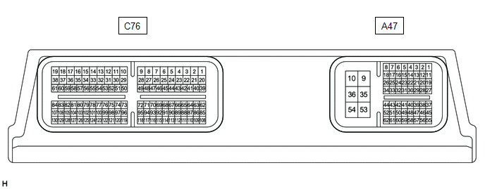
ECM
HINT:
The standard voltage and resistance between each pair of ECM terminals is shown in the table below.
The appropriate conditions for checking each pair of terminals are also indicated. The result of checks should be compared with the standard voltage or resistance for that pair of terminals shown in the "Specified Condition" column.
Use the illustration above as a reference for the ECM terminals.
|
Terminal No. (Symbol) |
Wiring Color |
Terminal Description |
Condition |
Specified Condition |
|---|---|---|---|---|
|
A47-9 (+B) - A47-10 (E1) |
BE - W-B |
Power source of ECM |
Engine switch on (IG) |
11 to 14 V |
|
A47-16 (NEO) - A47-10 (E1) |
BR - W-B |
Crankshaft position sensor signal to TCM |
Engine idling with warm engine |
Pulse generation |
|
A47-28 (ECCS) - A47-10 (E1) |
BR - W-B |
Shift paddle switch ground |
Always |
Below 1 Ω |
|
A47-31 (YZK) - A47-10 (E1) |
LG - W-B |
Drive mode select switch (combination switch assembly) signal |
|
11 to 14 V |
|
Below 1.5 V |
|||
|
A47-35 (+B2) - A47-10 (E1) |
BE - W-B |
Power source of ECM |
Engine switch on (IG) |
11 to 14 V |
|
A47-41 (DMS-) - A47-10 (E1) |
Y - W-B |
Drive mode select switch (combination switch assembly) signal |
|
11 to 14 V |
|
Below 1.5 V |
|||
|
C76-39 (CANN) - A47-10 (E1) |
V - W-B |
CAN communication line to TCM |
Engine switch on (IG) |
Pulse generation |
|
C76-40 (CANP) - A47-10 (E1) |
P - W-B |
CAN communication line to TCM |
Engine switch on (IG) |
Pulse generation |
|
|
|