|
8H-22 (FRCY) - Body ground
|
Front door courtesy light switch (for RH) input
|
Front door RH open → closed
|
Below 1 V → 11 to 14 V or pulse output (maximum 14 V)*3
|
|
8H-23 (FLCY) - Body ground
|
Front door courtesy light switch (for LH) input
|
Front door LH open → closed
|
Below 1 V → 11 to 14 V or pulse output (maximum 14 V)*3
|
|
8H-27 (RCTY) - Body ground
|
Rear door courtesy light switch (for RH) input
|
Rear door RH open → closed
|
Below 1 V → 11 to 14 V or pulse output (maximum 14 V)*3
|
|
8H-18 (LCTY) - Body ground
|
Rear door courtesy light switch (for LH) input
|
Rear door LH open → closed
|
Below 1 V → 11 to 14 V or pulse output (maximum 14 V)*3
|
|
8H-5 (BCTY) - Body ground*2
|
Back door courtesy light switch input
|
Back door open → closed
|
Below 1 V → 11 to 14 V or pulse output (maximum 14 V)*3
|
|
8H-5 (LGCY) -Body ground*1
|
Luggage compartment door courtesy light switch input
|
Luggage compartment door open → closed
|
Below 1 V → 11 to 14 V or pulse output (maximum 14 V)*3
|
|
8H-32 (TR+) - Body ground*2
|
Back door lock motor drive output
|
Back door closed → open
|
Below 1 V → 11 to 14 V → Below 1 V
|
|
8H-32 (TR+) - Body ground*1
|
Luggage compartment door lock motor drive output
|
Luggage compartment door closed → open
|
Below 1 V → 11 to 14 V → Below 1 V
|
|
8A-7 (ACTD) - Body ground
|
Door lock motor unlock drive output
|
Door control switch or driver door key cylinder off → on (unlock)
|
Below 1 V → 11 to 14 V → Below 1 V
|
|
8H-34 (ACT-) - Body ground
|
|
8H-35 (ACT-) - Body ground
|
|
8H-37 (ACT+) - Body ground
|
Door lock motor lock drive output
|
Door control switch or driver door key cylinder off → on (lock)
|
Below 1 V → 11 to 14 V → Below 1 V
|
|
I85-3 (LSFR) - Body ground
|
Front door RH unlock detection switch input
|
Front door RH unlocked → locked
|
Below 1 V → 11 to 14 V or pulse output (maximum 14 V)*3
|
|
I85-9 (LSFL) - Body ground
|
Front door LH unlock detection switch input
|
Front door LH unlocked → locked
|
Below 1 V → 11 to 14 V or pulse output (maximum 14 V)*3
|
|
I86-23 (LSWR) - Body ground
|
Rear door RH unlock detection switch input
|
Rear door RH unlocked → locked
|
Below 1 V → 11 to 14 V or pulse output (maximum 14 V)*3
|
|
I85-10 (LSWL) - Body ground
|
Rear door LH unlock detection switch input
|
Rear door LH unlocked → locked
|
Below 1 V → 11 to 14 V or pulse output (maximum 14 V)*3
|
|
I85-28 (L2) - Body ground
|
Driver door key-linked lock input
|
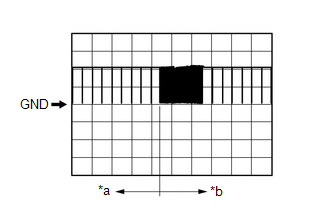
Driver door key cylinder turned to lock
|
Below 1 V
|
|
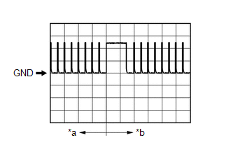
Driver door key cylinder not turned
|
Pulse generation
|
|
I85-4 (UL3) - Body ground
|
Driver door key-linked unlock input
|
Driver door key cylinder turned to unlock
|
Below 1 V
|
|
Driver door key cylinder not turned
|
Pulse generation
|
|
8F-13 (BZR) - Body ground*4
|
Wireless door lock buzzer output
|
Active Test Wireless Buzzer on → off
|
Pulse generation → Below 1 V
|