| Last Modified: 05-13-2024 | 6.11:8.1.0 | Doc ID: RM10000000289V7 |
| Model Year Start: 2023 | Model: GR Corolla | Prod Date Range: [11/2022 - ] |
| Title: SUPPLEMENTAL RESTRAINT SYSTEMS: AIRBAG SYSTEM: B00B500; Driver Seat Track Position Restraints Sensor Circuit Undetermined Failure; 2023 - 2025 MY Corolla Corolla Hatchback Corolla HV GR Corolla [11/2022 - ] | ||
|
DTC |
B00B500 |
Driver Seat Track Position Restraints Sensor Circuit Undetermined Failure |
DESCRIPTION
|
DTC No. |
Detection Item |
DTC Detection Condition |
Trouble Area |
Warning Indicate |
DTC Output from |
Priority |
Test Mode / Check Mode |
|---|---|---|---|---|---|---|---|
|
B00B500 |
Driver Seat Track Position Restraints Sensor Circuit Undetermined Failure |
When it is determined that the specified number of times or more is not achieved after the ignition switch is turned to ON. |
for TMC Made
for TMMMS Made
|
Comes on |
SRS Airbag |
A |
Does not apply to test/check mode |
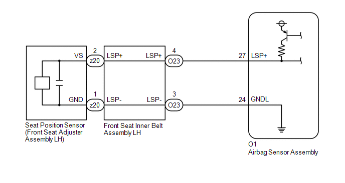
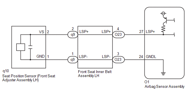
- *1: The seat position sensor is built into the front seat adjuster assembly LH.
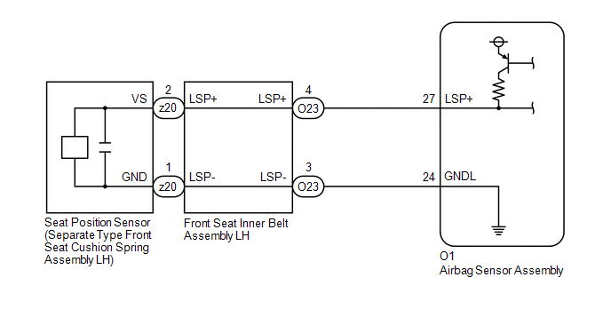
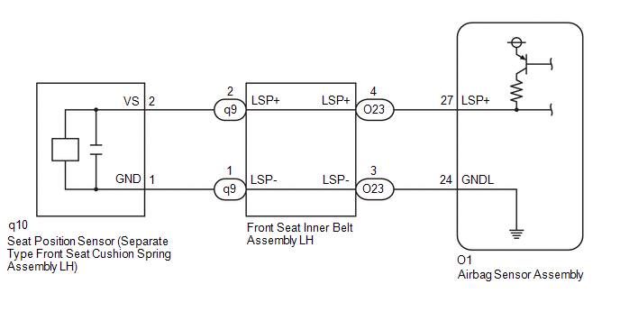
- *2: The seat position sensor is built into the separate type front seat cushion spring assembly LH.
WIRING DIAGRAM
for TMC Made Manual Seat:
for TMC Made Power Seat:
for TMMMS Made Manual Seat:
for TMMMS Made Power Seat:
CAUTION / NOTICE / HINT
NOTICE:
-
After the ignition switch is turned off, there may be a waiting time before disconnecting the negative (-) auxiliary battery terminal.
Click here
![2023 - 2025 MY Corolla Corolla Hatchback Corolla HV GR Corolla [09/2022 - ]; SETUP: WHEN DISCONNECTING OR RECONNECTING BATTERY TERMINAL: BEFORE DISCONNECTING BATTERY](/t3Portal/stylegraphics/info.gif)
HINT:
When disconnecting and reconnecting the auxiliary battery, there is an automatic learning function that completes learning when the respective system is used.
Click here
-
After replacing the airbag sensor assembly, refer to work procedure.
Click here
PROCEDURE
|
1. |
CHECK VEHICLE CONDITION |
(a) Choose the model to be inspected.
|
Result |
Proceed to |
|---|---|
|
for TMC Made Manual Seat |
A |
|
for TMC Made Power Seat |
B |
|
for TMMMS Made Manual Seat |
C |
|
for TMMMS Made Power Seat |
D |
| B |

|
| C |
|
| D |
|
|

|
2. |
CHECK CONNECTION OF CONNECTORS |
Pre-procedure1
(a) Turn the ignition switch off.
(b) Disconnect the cable from the negative (-) auxiliary battery terminal, and wait for at least 60 seconds.
Procedure1
(c) Check that the connectors are properly connected to the airbag sensor assembly and seat position sensor (front seat adjuster assembly LH).
OK:
The connectors are properly connected.
Post-procedure1
(d) None
| NG |
|
CONNECT CONNECTORS PROPERLY |
|
|
3. |
CHECK CONNECTORS |
Pre-procedure1
|
(a) Disconnect the airbag sensor assembly connector. |
|

(b) Disconnect the seat position sensor connector.
Procedure1
(c) Check that the terminals of the connectors are not deformed or damaged.
OK:
The terminals are not deformed or damaged.
Post-procedure1
(d) None
| NG |
|
REPLACE FRONT SEAT INNER BELT ASSEMBLY LH OR REPAIR OR REPLACE HARNESS OR CONNECTOR |
|
|
4. |
INSPECT SEAT POSITION SENSOR (FRONT SEAT ADJUSTER ASSEMBLY LH) |
Pre-procedure1
(a) Remove the seat position sensor (front seat adjuster assembly LH).
Click here
Procedure1
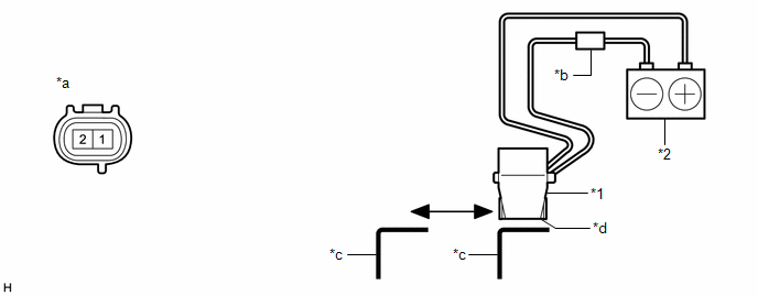
(b) Inspect the seat position sensor.
(1) Remove and reinsert the metal plate under the bottom face of the seat position sensor and measure the current value.
|
*1 |
Seat Position Sensor |
*2 |
Auxiliary battery |
|
*a |
Component without harness connected (Seat Position Sensor (Front Seat Adjuster Assembly LH)) |
*b |
Tester |
|
*c |
Metal plate |
*d |
Bottom Face |
Standard Current:
|
Tester Connection |
Condition |
Specified Condition |
|---|---|---|
|
Tester positive (+) - 1 Tester negative (-) - Auxiliary battery negative (-) |
Metal plate inserted |
4.7 to 7.3 mA |
|
Metal plate not inserted |
11.4 to 17.9 mA |
Post-procedure1
(c) None
| NG |
|
REPLACE SEAT POSITION SENSOR (FRONT SEAT ADJUSTER ASSEMBLY LH) |
|
|
5. |
CHECK SEAT POSITION SENSOR CIRCUIT (CHECK FOR OPEN IN THE CIRCUIT) |
Pre-procedure1
|
(a) Using a service wire, connect terminals 27 (LSP+) and 24 (GNDL) of connector B. NOTICE: Do not forcibly insert the service wire into the terminals of the connector when connecting a service wire. |
|
Procedure1
(b) Measure the resistance according to the value(s) in the table below.
Standard Resistance:
|
Tester Connection |
Condition |
Specified Condition |
|---|---|---|
|
z20-1 (GND) - z20-2 (VS) |
Always |
Below 1 Ω |
Post-procedure1
(c) Disconnect the service wire from connector B.
| NG |
|
|
|
6. |
CHECK SEAT POSITION SENSOR CIRCUIT (CHECK FOR SHORT TO GROUND IN THE CIRCUIT) |
|
(a) Measure the resistance according to the value(s) in the table below. Standard Resistance:
|
|
| NG |
|
|
|
7. |
CHECK SEAT POSITION SENSOR CIRCUIT (CHECK FOR SHORT TO +B IN THE CIRCUIT) |
Pre-procedure1
(a) Connect the cable to the negative (-) auxiliary battery terminal, and wait for at least 2 seconds.
(b) Turn the ignition switch to ON.
Procedure1
|
(c) Measure the voltage according to the value(s) in the table below. Standard Voltage:
Result:
|
|
Post-procedure1
(d) Turn the ignition switch off.
(e) Disconnect the cable from the negative (-) auxiliary battery terminal, and wait for at least 60 seconds.
| NG |
|
|
|
8. |
CLEAR DTC |
Pre-procedure1
|
(a) Connect the airbag sensor assembly connector. |
|
(b) Connect the seat position sensor (front seat adjuster assembly LH) connector.
(c) Connect the cable to the negative (-) auxiliary battery terminal, and wait for at least 2 seconds.
(d) Turn the ignition switch to ON, and wait for at least 60 seconds.
Procedure1
(e) Clear the DTCs stored in memory.
Body Electrical > SRS Airbag > Clear DTCs
Post-procedure1
(f) Turn the ignition switch off.
|
|
9. |
CHECK DTC |
Pre-procedure1
(a) Turn the ignition switch to ON, and wait for at least 60 seconds.
Procedure1
(b) Check for DTCs.
Body Electrical > SRS Airbag > Trouble Codes
|
Result |
Proceed to |
|---|---|
|
B00B500 is output |
A |
|
B00B500 is not output |
B |
HINT:
Codes other than DTC B00B500 may be output at this time, but they are not related to this check.
Post-procedure1
(c) None
| A |
|
| B |
|
|
10. |
CHECK CONNECTION OF CONNECTORS |
(a) Check that the connectors are properly connected to the front seat inner belt assembly LH.
OK:
The connectors are properly connected.
| NG |
|
CONNECT CONNECTORS PROPERLY |
|
|
11. |
CHECK CONNECTORS |
Pre-procedure1
|
(a) Disconnect the front seat inner belt assembly LH connector. |
|
Procedure1
(b) Check that the terminals of the connectors are not deformed or damaged.
OK:
The terminals are not deformed or damaged.
Post-procedure1
(c) None
| NG |
|
REPLACE FRONT SEAT INNER BELT ASSEMBLY LH OR REPAIR OR REPLACE HARNESS OR CONNECTOR |
|
|
12. |
CHECK HARNESS AND CONNECTOR (FRONT SEAT INNER BELT ASSEMBLY LH - AIRBAG SENSOR ASSEMBLY) |
Pre-procedure1
(a) Connect the cable to the negative (-) auxiliary battery terminal, and wait for at least 2 seconds.
(b) Turn the ignition switch to ON.
Procedure1
|
(c) Measure the voltage according to the value(s) in the table below. Standard Voltage:
Result:
|
|
Post-procedure1
(d) Turn the ignition switch off.
(e) Disconnect the cable from the negative (-) auxiliary battery terminal, and wait for at least 60 seconds.
| OK |
|
| NG |
|
REPAIR OR REPLACE HARNESS OR CONNECTOR |
|
13. |
CHECK CONNECTION OF CONNECTORS |
(a) Check that the connectors are properly connected to the front seat inner belt assembly LH.
OK:
The connectors are properly connected.
| NG |
|
CONNECT CONNECTORS PROPERLY |
|
|
14. |
CHECK CONNECTORS |
Pre-procedure1
|
(a) Disconnect the front seat inner belt assembly LH connector. |
|
Procedure1
(b) Check that the terminals of the connectors are not deformed or damaged.
OK:
The terminals are not deformed or damaged.
Post-procedure1
(c) None
| NG |
|
REPLACE FRONT SEAT INNER BELT ASSEMBLY LH OR REPAIR OR REPLACE HARNESS OR CONNECTOR |
|
|
15. |
CHECK HARNESS AND CONNECTOR (FRONT SEAT INNER BELT ASSEMBLY LH - AIRBAG SENSOR ASSEMBLY) |
|
(a) Measure the resistance according to the value(s) in the table below. Standard Resistance:
Result:
|
|
| OK |
|
| NG |
|
REPAIR OR REPLACE HARNESS OR CONNECTOR |
|
16. |
CHECK CONNECTION OF CONNECTORS |
(a) Check that the connectors are properly connected to the front seat inner belt assembly LH.
OK:
The connectors are properly connected.
| NG |
|
CONNECT CONNECTORS PROPERLY |
|
|
17. |
CHECK CONNECTORS |
Pre-procedure1
|
(a) Disconnect the front seat inner belt assembly LH connector. |
|
Procedure1
(b) Check that the terminals of the connectors are not deformed or damaged.
OK:
The terminals are not deformed or damaged.
Post-procedure1
(c) None
| NG |
|
REPLACE FRONT SEAT INNER BELT ASSEMBLY LH OR REPAIR OR REPLACE HARNESS OR CONNECTOR |
|
|
18. |
CHECK HARNESS AND CONNECTOR (FRONT SEAT INNER BELT ASSEMBLY LH - AIRBAG SENSOR ASSEMBLY) |
Pre-procedure1
(a) Using a service wire, connect terminals 27 (LSP+) and 24 (GNDL) of connector B.
NOTICE:
Do not forcibly insert the service wire into the terminals of the connector when connecting a service wire.
Procedure1
|
(b) Measure the resistance according to the value(s) in the table below. Standard Resistance:
Result:
|
|
Post-procedure1
(c) Disconnect the service wire from connector B.
| OK |
|
| NG |
|
REPAIR OR REPLACE HARNESS OR CONNECTOR |
|
19. |
CHECK CONNECTION OF CONNECTORS |
Pre-procedure1
(a) Turn the ignition switch off.
(b) Disconnect the cable from the negative (-) auxiliary battery terminal, and wait for at least 60 seconds.
Procedure1
(c) Check that the connectors are properly connected to the airbag sensor assembly and seat position sensor (front seat adjuster assembly LH).
OK:
The connectors are properly connected.
Post-procedure1
(d) None
| NG |
|
CONNECT CONNECTORS PROPERLY |
|
|
20. |
CHECK CONNECTORS |
Pre-procedure1
|
(a) Disconnect the airbag sensor assembly connector. |
|
(b) Disconnect the seat position sensor connector.
Procedure1
(c) Check that the terminals of the connectors are not deformed or damaged.
OK:
The terminals are not deformed or damaged.
Post-procedure1
(d) None
| NG |
|
REPAIR OR REPLACE HARNESS OR CONNECTOR |
|
|
21. |
INSPECT SEAT POSITION SENSOR (FRONT SEAT ADJUSTER ASSEMBLY LH) |
Pre-procedure1
(a) Remove the seat position sensor (front seat adjuster assembly LH).
Click here
Procedure1
(b) Inspect the seat position sensor.
(1) Remove and reinsert the metal plate under the bottom face of the seat position sensor and measure the current value.
|
*1 |
Seat Position Sensor |
*2 |
Auxiliary battery |
|
*a |
Component without harness connected (Seat Position Sensor (Front Seat Adjuster Assembly LH)) |
*b |
Tester |
|
*c |
Metal plate |
*d |
Bottom Face |
Standard Current:
|
Tester Connection |
Condition |
Specified Condition |
|---|---|---|
|
Tester positive (+) - 1 Tester negative (-) - Auxiliary battery negative (-) |
Metal plate inserted |
4.7 to 7.3 mA |
|
Metal plate not inserted |
11.4 to 17.9 mA |
Post-procedure1
(c) None
| NG |
|
REPLACE SEAT POSITION SENSOR (FRONT SEAT ADJUSTER ASSEMBLY LH) |
|
|
22. |
CHECK SEAT POSITION SENSOR CIRCUIT (CHECK FOR OPEN IN THE CIRCUIT) |
Pre-procedure1
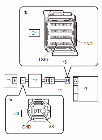
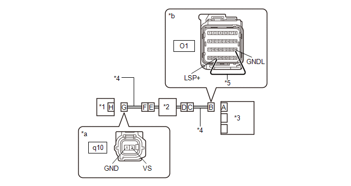
(a) Using a service wire, connect terminals 27 (LSP+) and 24 (GNDL) of connector B.
NOTICE:
Do not forcibly insert the service wire into the terminals of the connector when connecting a service wire.
|
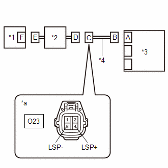
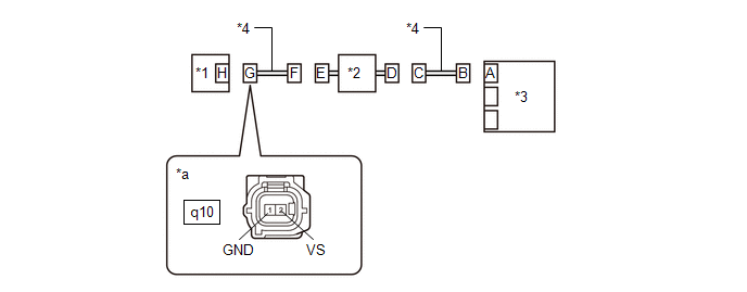
*1 |
Seat Position Sensor (Front Seat Adjuster Assembly LH) |
*2 |
Front Seat Inner Belt Assembly LH |
|
*3 |
Airbag Sensor Assembly |
*4 |
Wire Harness |
|
*5 |
Service Wire |
- |
- |
|
*a |
Front view of wire harness connector (to Seat Position Sensor (Front Seat Adjuster Assembly LH)) |
*b |
Front view of wire harness connector (to Airbag Sensor Assembly) |
Procedure1
(b) Measure the resistance according to the value(s) in the table below.
Standard Resistance:
|
Tester Connection |
Condition |
Specified Condition |
|---|---|---|
|
q10-1 (GND) - q10-2 (VS) |
Always |
Below 1 Ω |
Post-procedure1
(c) Disconnect the service wire from connector B.
| NG |
|
|
|
23. |
CHECK SEAT POSITION SENSOR CIRCUIT (CHECK FOR SHORT TO GROUND IN THE CIRCUIT) |
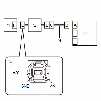
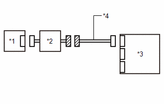
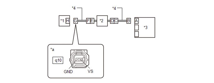
(a) Measure the resistance according to the value(s) in the table below.
|
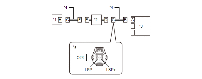
*1 |
Seat Position Sensor (Front Seat Adjuster Assembly LH) |
*2 |
Front Seat Inner Belt Assembly LH |
|
*3 |
Airbag Sensor Assembly |
*4 |
Wire Harness |
|
*a |
Front view of wire harness connector (to Seat Position Sensor (Front Seat Adjuster Assembly LH)) |
- |
- |
Standard Resistance:
|
Tester Connection |
Condition |
Specified Condition |
|---|---|---|
|
q10-1 (GND) - Body ground |
Always |
1 MΩ or higher |
|
q10-2 (VS) - Body ground |
Always |
1 MΩ or higher |
| NG |
|
|
|
24. |
CHECK SEAT POSITION SENSOR CIRCUIT (CHECK FOR SHORT TO +B IN THE CIRCUIT) |
Pre-procedure1
(a) Connect the cable to the negative (-) auxiliary battery terminal, and wait for at least 2 seconds.
(b) Turn the ignition switch to ON.
Procedure1
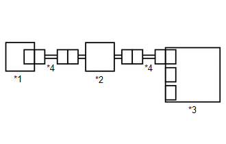
(c) Measure the voltage according to the value(s) in the table below.
|
*1 |
Seat Position Sensor (Front Seat Adjuster Assembly LH) |
*2 |
Front Seat Inner Belt Assembly LH |
|
*3 |
Airbag Sensor Assembly |
*4 |
Wire Harness |
|
*a |
Front view of wire harness connector (to Seat Position Sensor (Front Seat Adjuster Assembly LH)) |
- |
- |
Standard Voltage:
|
Tester Connection |
Condition |
Specified Condition |
|---|---|---|
|
q10-1 (GND) - Body ground |
Ignition switch ON |
Below 1 V |
|
q10-2 (VS) - Body ground |
Ignition switch ON |
Below 1 V |
Post-procedure1
(d) Turn the ignition switch off.
(e) Disconnect the cable from the negative (-) auxiliary battery terminal, and wait for at least 60 seconds.
| NG |
|
|
|
25. |
CLEAR DTC |
Pre-procedure1
|
(a) Connect the airbag sensor assembly connector. |
|
(b) Connect the seat position sensor (front seat adjuster assembly LH) connector.
(c) Connect the cable to the negative (-) auxiliary battery terminal, and wait for at least 2 seconds.
(d) Turn the ignition switch to ON, and wait for at least 60 seconds.
Procedure1
(e) Clear the DTCs stored in memory.
Body Electrical > SRS Airbag > Clear DTCs
Post-procedure1
(f) Turn the ignition switch off.
|
|
26. |
CHECK DTC |
Pre-procedure1
(a) Turn the ignition switch to ON, and wait for at least 60 seconds.
Procedure1
(b) Check for DTCs.
Body Electrical > SRS Airbag > Trouble Codes
|
Result |
Proceed to |
|---|---|
|
B00B500 is output |
A |
|
B00B500 is not output |
B |
HINT:
Codes other than DTC B00B500 may be output at this time, but they are not related to this check.
Post-procedure1
(c) None
| A |
|
| B |
|
|
27. |
CHECK CONNECTION OF CONNECTORS |
(a) Check that the connectors are properly connected to the front seat inner belt assembly LH.
OK:
The connectors are properly connected.
| NG |
|
CONNECT CONNECTORS PROPERLY |
|
|
28. |
CHECK CONNECTORS |
Pre-procedure1
|
(a) Disconnect the front seat inner belt assembly LH connector. |
|
Procedure1
(b) Check that the terminals of the connectors are not deformed or damaged.
OK:
The terminals are not deformed or damaged.
Post-procedure1
(c) None
| NG |
|
REPLACE FRONT SEAT INNER BELT ASSEMBLY LH OR REPAIR OR REPLACE HARNESS OR CONNECTOR |
|
|
29. |
CHECK HARNESS AND CONNECTOR (SEAT POSITION SENSOR - FRONT SEAT INNER BELT ASSEMBLY LH) |
Pre-procedure1
(a) Connect the cable to the negative (-) auxiliary battery terminal, and wait for at least 2 seconds.
(b) Turn the ignition switch to ON.
Procedure1
(c) Measure the voltage according to the value(s) in the table below.
|
*1 |
Seat Position Sensor (Front Seat Adjuster Assembly LH) |
*2 |
Front Seat Inner Belt Assembly LH |
|
*3 |
Airbag Sensor Assembly |
*4 |
Wire Harness |
|
*a |
Front view of wire harness connector (to Seat Position Sensor (Front Seat Adjuster Assembly LH)) |
- |
- |
Standard Voltage:
|
Tester Connection |
Condition |
Specified Condition |
|---|---|---|
|
q10-2 (VS) - Body ground |
Ignition switch ON |
Below 1 V |
|
q10-1 (GND) - Body ground |
Ignition switch ON |
Below 1 V |
Post-procedure1
(d) Turn the ignition switch off.
(e) Disconnect the cable from the negative (-) auxiliary battery terminal, and wait for at least 60 seconds.
| NG |
|
REPAIR OR REPLACE HARNESS OR CONNECTOR |
|
|
30. |
CHECK HARNESS AND CONNECTOR (FRONT SEAT INNER BELT ASSEMBLY LH - AIRBAG SENSOR ASSEMBLY) |
Pre-procedure1
(a) Connect the cable to the negative (-) auxiliary battery terminal, and wait for at least 2 seconds.
(b) Turn the ignition switch to ON.
Procedure1
(c) Measure the voltage according to the value(s) in the table below.
|
*1 |
Seat Position Sensor (Front Seat Adjuster Assembly LH) |
*2 |
Front Seat Inner Belt Assembly LH |
|
*3 |
Airbag Sensor Assembly |
*4 |
Wire Harness |
|
*a |
Front view of wire harness connector (to Front Seat Inner Belt Assembly LH) |
- |
- |
Standard Voltage:
|
Tester Connection |
Condition |
Specified Condition |
|---|---|---|
|
O23-4 (LSP+) - Body ground |
Ignition switch ON |
Below 1 V |
|
O23-3 (LSP-) - Body ground |
Ignition switch ON |
Below 1 V |
Post-procedure1
(d) Turn the ignition switch off.
(e) Disconnect the cable from the negative (-) auxiliary battery terminal, and wait for at least 60 seconds.
| OK |
|
| NG |
|
REPAIR OR REPLACE HARNESS OR CONNECTOR |
|
31. |
CHECK CONNECTION OF CONNECTORS |
(a) Check that the connectors are properly connected to the front seat inner belt assembly LH.
OK:
The connectors are properly connected.
| NG |
|
CONNECT CONNECTORS PROPERLY |
|
|
32. |
CHECK CONNECTORS |
Pre-procedure1
|
(a) Disconnect the front seat inner belt assembly LH connector. |
|
Procedure1
(b) Check that the terminals of the connectors are not deformed or damaged.
OK:
The terminals are not deformed or damaged.
Post-procedure1
(c) None
| NG |
|
REPLACE FRONT SEAT INNER BELT ASSEMBLY LH OR REPAIR OR REPLACE HARNESS OR CONNECTOR |
|
|
33. |
CHECK HARNESS AND CONNECTOR (SEAT POSITION SENSOR - FRONT SEAT INNER BELT ASSEMBLY LH) |
(a) Measure the resistance according to the value(s) in the table below.
|
*1 |
Seat Position Sensor (Front Seat Adjuster Assembly LH) |
*2 |
Front Seat Inner Belt Assembly LH |
|
*3 |
Airbag Sensor Assembly |
*4 |
Wire Harness |
|
*a |
Front view of wire harness connector (to Seat Position Sensor (Front Seat Adjuster Assembly LH)) |
- |
- |
Standard Resistance:
|
Tester Connection |
Condition |
Specified Condition |
|---|---|---|
|
q10-2 (VS) - Body ground |
Always |
1 MΩ or higher |
|
q10-1 (GND) - Body ground |
Always |
1 MΩ or higher |
| NG |
|
REPAIR OR REPLACE HARNESS OR CONNECTOR |
|
|
34. |
CHECK HARNESS AND CONNECTOR (FRONT SEAT INNER BELT ASSEMBLY LH - AIRBAG SENSOR ASSEMBLY) |
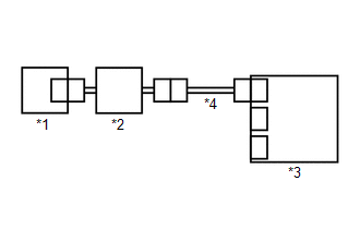
(a) Measure the resistance according to the value(s) in the table below.
|
*1 |
Seat Position Sensor (Front Seat Adjuster Assembly LH) |
*2 |
Front Seat Inner Belt Assembly LH |
|
*3 |
Airbag Sensor Assembly |
*4 |
Wire Harness |
|
*a |
Front view of wire harness connector (to Front Seat Inner Belt Assembly LH) |
- |
- |
Standard Resistance:
|
Tester Connection |
Condition |
Specified Condition |
|---|---|---|
|
O23-4 (LSP+) - Body ground |
Always |
1 MΩ or higher |
|
O23-3 (LSP-) - Body ground |
Always |
1 MΩ or higher |
| OK |
|
| NG |
|
REPAIR OR REPLACE HARNESS OR CONNECTOR |
|
35. |
CHECK CONNECTION OF CONNECTORS |
(a) Check that the connectors are properly connected to the front seat inner belt assembly LH.
OK:
The connectors are properly connected.
| NG |
|
CONNECT CONNECTORS PROPERLY |
|
|
36. |
CHECK CONNECTORS |
Pre-procedure1
|
(a) Disconnect the front seat inner belt assembly LH connector. |
|
Procedure1
(b) Check that the terminals of the connectors are not deformed or damaged.
OK:
The terminals are not deformed or damaged.
Post-procedure1
(c) None
| NG |
|
REPLACE FRONT SEAT INNER BELT ASSEMBLY LH OR REPAIR OR REPLACE HARNESS OR CONNECTOR |
|
|
37. |
CHECK HARNESS AND CONNECTOR (SEAT POSITION SENSOR - FRONT SEAT INNER BELT ASSEMBLY LH) |
Pre-procedure1
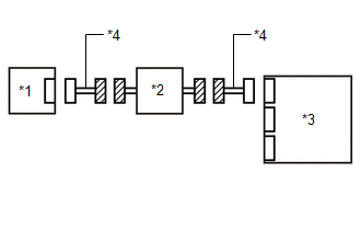
(a) Using a service wire, connect terminals 2 (LSP+) and 1 (LSP-) of connector F.
NOTICE:
Do not forcibly insert the service wire into the terminals of the connector when connecting a service wire.
Procedure1
(b) Measure the resistance according to the value(s) in the table below.
|
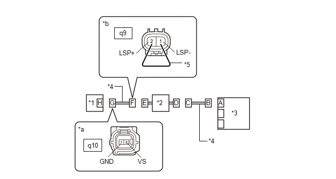
*1 |
Seat Position Sensor (Front Seat Adjuster Assembly LH) |
*2 |
Front Seat Inner Belt Assembly LH |
|
*3 |
Airbag Sensor Assembly |
*4 |
Wire Harness |
|
*5 |
Service Wire |
- |
- |
|
*a |
Front view of wire harness connector (to Seat Position Sensor (Front Seat Adjuster Assembly LH)) |
*b |
Front view of wire harness connector (to Front Seat Inner Belt Assembly LH) |
Standard Resistance:
|
Tester Connection |
Condition |
Specified Condition |
|---|---|---|
|
q10-2 (VS) - q10-1 (GND) |
Always |
Below 1 Ω |
Post-procedure1
(c) Disconnect the service wire from connector F.
| NG |
|
REPAIR OR REPLACE HARNESS OR CONNECTOR |
|
|
38. |
CHECK HARNESS AND CONNECTOR (FRONT SEAT INNER BELT ASSEMBLY LH - AIRBAG SENSOR ASSEMBLY) |
Pre-procedure1
(a) Using a service wire, connect terminals 27 (LSP+) and 24 (GNDL) of connector B.
NOTICE:
Do not forcibly insert the service wire into the terminals of the connector when connecting a service wire.
Procedure1
(b) Measure the resistance according to the value(s) in the table below.
|
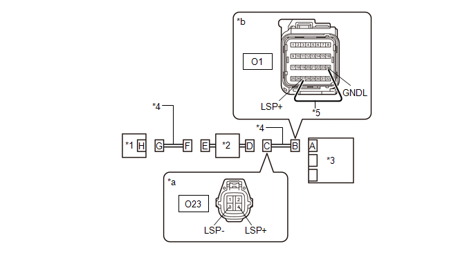
*1 |
Seat Position Sensor (Front Seat Adjuster Assembly LH) |
*2 |
Front Seat Inner Belt Assembly LH |
|
*3 |
Airbag Sensor Assembly |
*4 |
Wire Harness |
|
*5 |
Service Wire |
- |
- |
|
*a |
Front view of wire harness connector (to Front Seat Inner Belt Assembly LH) |
*b |
Front view of wire harness connector (to Airbag Sensor Assembly) |
Standard Resistance:
|
Tester Connection |
Condition |
Specified Condition |
|---|---|---|
|
O23-4 (LSP+) - O23-3 (LSP-) |
Always |
Below 1 Ω |
Post-procedure1
(c) Disconnect the service wire from connector B.
| OK |
|
| NG |
|
REPAIR OR REPLACE HARNESS OR CONNECTOR |
|
39. |
CHECK CONNECTION OF CONNECTORS |
Pre-procedure1
(a) Turn the ignition switch off.
(b) Disconnect the cable from the negative (-) auxiliary battery terminal, and wait for at least 60 seconds.
Procedure1
(c) Check that the connectors are properly connected to the airbag sensor assembly and seat position sensor (separate type front seat cushion spring assembly LH).
OK:
The connectors are properly connected.
Post-procedure1
(d) None
| NG |
|
CONNECT CONNECTORS PROPERLY |
|
|
40. |
CHECK CONNECTORS |
Pre-procedure1
|
(a) Disconnect the airbag sensor assembly connector. |
|
(b) Disconnect the seat position sensor connector.
Procedure1
(c) Check that the terminals of the connectors are not deformed or damaged.
OK:
The terminals are not deformed or damaged.
Post-procedure1
(d) None
| NG |
|
REPLACE FRONT SEAT INNER BELT ASSEMBLY LH OR REPAIR OR REPLACE HARNESS OR CONNECTOR |
|
|
41. |
INSPECT SEAT POSITION SENSOR (SEPARATE TYPE FRONT SEAT CUSHION SPRING ASSEMBLY LH) |
Pre-procedure1
(a) Remove the seat position sensor (separate type front seat cushion spring assembly LH).
Click here
Procedure1
(b) Inspect the seat position sensor.
(1) Remove and reinsert the metal plate under the bottom face of the seat position sensor and measure the current value.
|
*1 |
Seat Position Sensor |
*2 |
Auxiliary battery |
|
*a |
Component without harness connected (Seat Position Sensor (Separate Type Front Seat Cushion Spring Assembly LH)) |
*b |
Tester |
|
*c |
Metal plate |
*d |
Bottom Face |
Standard Current:
|
Tester Connection |
Condition |
Specified Condition |
|---|---|---|
|
Tester positive (+) - 1 Tester negative (-) - Auxiliary battery negative (-) |
Metal plate inserted |
4.7 to 7.3 mA |
|
Metal plate not inserted |
11.4 to 17.9 mA |
Post-procedure1
(c) None
| NG |
|
REPLACE SEAT POSITION SENSOR (SEPARATE TYPE FRONT SEAT CUSHION SPRING ASSEMBLY LH) |
|
|
42. |
CHECK SEAT POSITION SENSOR CIRCUIT (CHECK FOR OPEN IN THE CIRCUIT) |
Pre-procedure1
|
(a) Using a service wire, connect terminals 27 (LSP+) and 24 (GNDL) of connector B. NOTICE: Do not forcibly insert the service wire into the terminals of the connector when connecting a service wire. |
|
Procedure1
(b) Measure the resistance according to the value(s) in the table below.
Standard Resistance:
|
Tester Connection |
Condition |
Specified Condition |
|---|---|---|
|
z20-1 (GND) - z20-2 (VS) |
Always |
Below 1 Ω |
Post-procedure1
(c) Disconnect the service wire from connector B.
| NG |
|
|
|
43. |
CHECK SEAT POSITION SENSOR CIRCUIT (CHECK FOR SHORT TO GROUND IN THE CIRCUIT) |
|
(a) Measure the resistance according to the value(s) in the table below. Standard Resistance:
|
|
| NG |
|
|
|
44. |
CHECK SEAT POSITION SENSOR CIRCUIT (CHECK FOR SHORT TO +B IN THE CIRCUIT) |
Pre-procedure1
(a) Connect the cable to the negative (-) auxiliary battery terminal, and wait for at least 2 seconds.
(b) Turn the ignition switch to ON.
Procedure1
|
(c) Measure the voltage according to the value(s) in the table below. Standard Voltage:
Result:
|
|
Post-procedure1
(d) Turn the ignition switch off.
(e) Disconnect the cable from the negative (-) auxiliary battery terminal, and wait for at least 60 seconds.
| NG |
|
|
|
45. |
CLEAR DTC |
Pre-procedure1
|
(a) Connect the airbag sensor assembly connector. |
|
(b) Connect the seat position sensor (separate type front seat cushion spring assembly LH) connector.
(c) Connect the cable to the negative (-) auxiliary battery terminal, and wait for at least 2 seconds.
(d) Turn the ignition switch to ON, and wait for at least 60 seconds.
Procedure1
(e) Clear the DTCs stored in memory.
Body Electrical > SRS Airbag > Clear DTCs
Post-procedure1
(f) Turn the ignition switch off.
|
|
46. |
CHECK DTC |
Pre-procedure1
(a) Turn the ignition switch to ON, and wait for at least 60 seconds.
Procedure1
(b) Check for DTCs.
Body Electrical > SRS Airbag > Trouble Codes
|
Result |
Proceed to |
|---|---|
|
B00B500 is output |
A |
|
B00B500 is not output |
B |
HINT:
Codes other than DTC B00B500 may be output at this time, but they are not related to this check.
Post-procedure1
(c) None
| A |
|
| B |
|
|
47. |
CHECK CONNECTION OF CONNECTORS |
(a) Check that the connectors are properly connected to the front seat inner belt assembly LH.
OK:
The connectors are properly connected.
| NG |
|
CONNECT CONNECTORS PROPERLY |
|
|
48. |
CHECK CONNECTORS |
Pre-procedure1
|
(a) Disconnect the front seat inner belt assembly LH connector. |
|
Procedure1
(b) Check that the terminals of the connectors are not deformed or damaged.
OK:
The terminals are not deformed or damaged.
Post-procedure1
(c) None
| NG |
|
REPLACE FRONT SEAT INNER BELT ASSEMBLY LH OR REPAIR OR REPLACE HARNESS OR CONNECTOR |
|
|
49. |
CHECK HARNESS AND CONNECTOR (FRONT SEAT INNER BELT ASSEMBLY LH - AIRBAG SENSOR ASSEMBLY) |
Pre-procedure1
(a) Connect the cable to the negative (-) auxiliary battery terminal, and wait for at least 2 seconds.
(b) Turn the ignition switch to ON.
Procedure1
|
(c) Measure the voltage according to the value(s) in the table below. Standard Voltage:
Result:
|
|
Post-procedure1
(d) Turn the ignition switch off.
(e) Disconnect the cable from the negative (-) auxiliary battery terminal, and wait for at least 60 seconds.
| OK |
|
| NG |
|
REPAIR OR REPLACE HARNESS OR CONNECTOR |
|
50. |
CHECK CONNECTION OF CONNECTORS |
(a) Check that the connectors are properly connected to the front seat inner belt assembly LH.
OK:
The connectors are properly connected.
| NG |
|
CONNECT CONNECTORS PROPERLY |
|
|
51. |
CHECK CONNECTORS |
Pre-procedure1
|
(a) Disconnect the front seat inner belt assembly LH connector. |
|
Procedure1
(b) Check that the terminals of the connectors are not deformed or damaged.
OK:
The terminals are not deformed or damaged.
Post-procedure1
(c) None
| NG |
|
REPLACE FRONT SEAT INNER BELT ASSEMBLY LH OR REPAIR OR REPLACE HARNESS OR CONNECTOR |
|
|
52. |
CHECK HARNESS AND CONNECTOR (FRONT SEAT INNER BELT ASSEMBLY LH - AIRBAG SENSOR ASSEMBLY) |
|
(a) Measure the resistance according to the value(s) in the table below. Standard Resistance:
Result:
|
|
| OK |
|
| NG |
|
REPAIR OR REPLACE HARNESS OR CONNECTOR |
|
53. |
CHECK CONNECTION OF CONNECTORS |
(a) Check that the connectors are properly connected to the front seat inner belt assembly LH.
OK:
The connectors are properly connected.
| NG |
|
CONNECT CONNECTORS PROPERLY |
|
|
54. |
CHECK CONNECTORS |
Pre-procedure1
|
(a) Disconnect the front seat inner belt assembly LH connector. |
|
Procedure1
(b) Check that the terminals of the connectors are not deformed or damaged.
OK:
The terminals are not deformed or damaged.
Post-procedure1
(c) None
| NG |
|
REPLACE FRONT SEAT INNER BELT ASSEMBLY LH OR REPAIR OR REPLACE HARNESS OR CONNECTOR |
|
|
55. |
CHECK HARNESS AND CONNECTOR (FRONT SEAT INNER BELT ASSEMBLY LH - AIRBAG SENSOR ASSEMBLY) |
Pre-procedure1
(a) Using a service wire, connect terminals 27 (LSP+) and 24 (GNDL) of connector B.
NOTICE:
Do not forcibly insert the service wire into the terminals of the connector when connecting a service wire.
Procedure1
|
(b) Measure the resistance according to the value(s) in the table below. Standard Resistance:
Result:
|
|
Post-procedure1
(c) Disconnect the service wire from connector B.
| OK |
|
| NG |
|
REPAIR OR REPLACE HARNESS OR CONNECTOR |
|
56. |
CHECK CONNECTION OF CONNECTORS |
Pre-procedure1
(a) Turn the ignition switch off.
(b) Disconnect the cable from the negative (-) auxiliary battery terminal, and wait for at least 60 seconds.
Procedure1
(c) Check that the connectors are properly connected to the airbag sensor assembly and seat position sensor (separate type front seat cushion spring assembly LH).
OK:
The connectors are properly connected.
Post-procedure1
(d) None
| NG |
|
CONNECT CONNECTORS PROPERLY |
|
|
57. |
CHECK CONNECTORS |
Pre-procedure1
|
(a) Disconnect the airbag sensor assembly connector. |
|
(b) Disconnect the seat position sensor connector.
Procedure1
(c) Check that the terminals of the connectors are not deformed or damaged.
OK:
The terminals are not deformed or damaged.
Post-procedure1
(d) None
| NG |
|
REPAIR OR REPLACE HARNESS OR CONNECTOR |
|
|
58. |
INSPECT SEAT POSITION SENSOR (SEPARATE TYPE FRONT SEAT CUSHION SPRING ASSEMBLY LH) |
Pre-procedure1
(a) Remove the seat position sensor (separate type front seat cushion spring assembly LH).
Click here
Procedure1
(b) Inspect the seat position sensor.
(1) Remove and reinsert the metal plate under the bottom face of the seat position sensor and measure the current value.
|
*1 |
Seat Position Sensor |
*2 |
Auxiliary battery |
|
*a |
Component without harness connected (Seat Position Sensor (Separate Type Front Seat Cushion Spring Assembly LH)) |
*b |
Tester |
|
*c |
Metal plate |
*d |
Bottom Face |
Standard Current:
|
Tester Connection |
Condition |
Specified Condition |
|---|---|---|
|
Tester positive (+) - 1 Tester negative (-) - Auxiliary battery negative (-) |
Metal plate inserted |
4.7 to 7.3 mA |
|
Metal plate not inserted |
11.4 to 17.9 mA |
Post-procedure1
(c) None
| NG |
|
REPLACE SEAT POSITION SENSOR (SEPARATE TYPE FRONT SEAT CUSHION SPRING ASSEMBLY LH) |
|
|
59. |
CHECK SEAT POSITION SENSOR CIRCUIT (CHECK FOR OPEN IN THE CIRCUIT) |
Pre-procedure1
(a) Using a service wire, connect terminals 27 (LSP+) and 24 (GNDL) of connector B.
NOTICE:
Do not forcibly insert the service wire into the terminals of the connector when connecting a service wire.
|
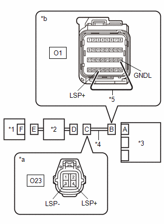
*1 |
Seat Position Sensor (Separate Type Front Seat Cushion Spring Assembly LH) |
*2 |
Front Seat Inner Belt Assembly LH |
|
*3 |
Airbag Sensor Assembly |
*4 |
Wire Harness |
|
*5 |
Service Wire |
- |
- |
|
*a |
Front view of wire harness connector (to Seat Position Sensor (Separate Type Front Seat Cushion Spring Assembly LH)) |
*b |
Front view of wire harness connector (to Airbag Sensor Assembly) |
Procedure1
(b) Measure the resistance according to the value(s) in the table below.
Standard Resistance:
|
Tester Connection |
Condition |
Specified Condition |
|---|---|---|
|
q10-1 (GND) - q10-2 (VS) |
Always |
Below 1 Ω |
Post-procedure1
(c) Disconnect the service wire from connector B.
| NG |
|
|
|
60. |
CHECK SEAT POSITION SENSOR CIRCUIT (CHECK FOR SHORT TO GROUND IN THE CIRCUIT) |
(a) Measure the resistance according to the value(s) in the table below.
|
*1 |
Seat Position Sensor (Separate Type Front Seat Cushion Spring Assembly LH) |
*2 |
Front Seat Inner Belt Assembly LH |
|
*3 |
Airbag Sensor Assembly |
*4 |
Wire Harness |
|
*a |
Front view of wire harness connector (to Seat Position Sensor (Separate Type Front Seat Cushion Spring Assembly LH)) |
- |
- |
Standard Resistance:
|
Tester Connection |
Condition |
Specified Condition |
|---|---|---|
|
q10-1 (GND) - Body ground |
Always |
1 MΩ or higher |
|
q10-2 (VS) - Body ground |
Always |
1 MΩ or higher |
| NG |
|
|
|
61. |
CHECK SEAT POSITION SENSOR CIRCUIT (CHECK FOR SHORT TO +B IN THE CIRCUIT) |
Pre-procedure1
(a) Connect the cable to the negative (-) auxiliary battery terminal, and wait for at least 2 seconds.
(b) Turn the ignition switch to ON.
Procedure1
(c) Measure the voltage according to the value(s) in the table below.
|
*1 |
Seat Position Sensor (Separate Type Front Seat Cushion Spring Assembly LH) |
*2 |
Front Seat Inner Belt Assembly LH |
|
*3 |
Airbag Sensor Assembly |
*4 |
Wire Harness |
|
*a |
Front view of wire harness connector (to Seat Position Sensor (Separate Type Front Seat Cushion Spring Assembly LH)) |
- |
- |
Standard Voltage:
|
Tester Connection |
Condition |
Specified Condition |
|---|---|---|
|
q10-1 (GND) - Body ground |
Ignition switch ON |
Below 1 V |
|
q10-2 (VS) - Body ground |
Ignition switch ON |
Below 1 V |
Post-procedure1
(d) Turn the ignition switch off.
(e) Disconnect the cable from the negative (-) auxiliary battery terminal, and wait for at least 60 seconds.
| NG |
|
|
|
62. |
CLEAR DTC |
Pre-procedure1
|
(a) Connect the airbag sensor assembly connector. |
|
(b) Connect the seat position sensor (separate type front seat cushion spring assembly LH) connector.
(c) Connect the cable to the negative (-) auxiliary battery terminal, and wait for at least 2 seconds.
(d) Turn the ignition switch to ON, and wait for at least 60 seconds.
Procedure1
(e) Clear the DTCs stored in memory.
Body Electrical > SRS Airbag > Clear DTCs
Post-procedure1
(f) Turn the ignition switch off.
|
|
63. |
CHECK DTC |
Pre-procedure1
(a) Turn the ignition switch to ON, and wait for at least 60 seconds.
Procedure1
(b) Check for DTCs.
Body Electrical > SRS Airbag > Trouble Codes
|
Result |
Proceed to |
|---|---|
|
B00B500 is output |
A |
|
B00B500 is not output |
B |
HINT:
Codes other than DTC B00B500 may be output at this time, but they are not related to this check.
Post-procedure1
(c) None
| A |
|
| B |
|
|
64. |
CHECK CONNECTION OF CONNECTORS |
(a) Check that the connectors are properly connected to the front seat inner belt assembly LH.
OK:
The connectors are properly connected.
| NG |
|
CONNECT CONNECTORS PROPERLY |
|
|
65. |
CHECK CONNECTORS |
Pre-procedure1
|
(a) Disconnect the front seat inner belt assembly LH connector. |
|
Procedure1
(b) Check that the terminals of the connectors are not deformed or damaged.
OK:
The terminals are not deformed or damaged.
Post-procedure1
(c) None
| NG |
|
REPLACE FRONT SEAT INNER BELT ASSEMBLY LH OR REPAIR OR REPLACE HARNESS OR CONNECTOR |
|
|
66. |
CHECK HARNESS AND CONNECTOR (SEAT POSITION SENSOR - FRONT SEAT INNER BELT ASSEMBLY LH) |
Pre-procedure1
(a) Connect the cable to the negative (-) auxiliary battery terminal, and wait for at least 2 seconds.
(b) Turn the ignition switch to ON.
Procedure1
(c) Measure the voltage according to the value(s) in the table below.
|
*1 |
Seat Position Sensor (Separate Type Front Seat Cushion Spring Assembly LH) |
*2 |
Front Seat Inner Belt Assembly LH |
|
*3 |
Airbag Sensor Assembly |
*4 |
Wire Harness |
|
*a |
Front view of wire harness connector (to Seat Position Sensor (Separate Type Front Seat Cushion Spring Assembly LH)) |
- |
- |
Standard Voltage:
|
Tester Connection |
Condition |
Specified Condition |
|---|---|---|
|
q10-2 (VS) - Body ground |
Ignition switch ON |
Below 1 V |
|
q10-1 (GND) - Body ground |
Ignition switch ON |
Below 1 V |
Post-procedure1
(d) Turn the ignition switch off.
(e) Disconnect the cable from the negative (-) auxiliary battery terminal, and wait for at least 60 seconds.
| NG |
|
REPAIR OR REPLACE HARNESS OR CONNECTOR |
|
|
67. |
CHECK HARNESS AND CONNECTOR (FRONT SEAT INNER BELT ASSEMBLY LH - AIRBAG SENSOR ASSEMBLY) |
Pre-procedure1
(a) Connect the cable to the negative (-) auxiliary battery terminal, and wait for at least 2 seconds.
(b) Turn the ignition switch to ON.
Procedure1
(c) Measure the voltage according to the value(s) in the table below.
|
*1 |
Seat Position Sensor (Separate Type Front Seat Cushion Spring Assembly LH) |
*2 |
Front Seat Inner Belt Assembly LH |
|
*3 |
Airbag Sensor Assembly |
*4 |
Wire Harness |
|
*a |
Front view of wire harness connector (to Front Seat Inner Belt Assembly LH) |
- |
- |
Standard Voltage:
|
Tester Connection |
Condition |
Specified Condition |
|---|---|---|
|
O23-4 (LSP+) - Body ground |
Ignition switch ON |
Below 1 V |
|
O23-3 (LSP-) - Body ground |
Ignition switch ON |
Below 1 V |
Post-procedure1
(d) Turn the ignition switch off.
(e) Disconnect the cable from the negative (-) auxiliary battery terminal, and wait for at least 60 seconds.
| OK |
|
| NG |
|
REPAIR OR REPLACE HARNESS OR CONNECTOR |
|
68. |
CHECK CONNECTION OF CONNECTORS |
(a) Check that the connectors are properly connected to the front seat inner belt assembly LH.
OK:
The connectors are properly connected.
| NG |
|
CONNECT CONNECTORS PROPERLY |
|
|
69. |
CHECK CONNECTORS |
Pre-procedure1
|
(a) Disconnect the front seat inner belt assembly LH connector. |
|
Procedure1
(b) Check that the terminals of the connectors are not deformed or damaged.
OK:
The terminals are not deformed or damaged.
Post-procedure1
(c) None
| NG |
|
REPLACE FRONT SEAT INNER BELT ASSEMBLY LH OR REPAIR OR REPLACE HARNESS OR CONNECTOR |
|
|
70. |
CHECK HARNESS AND CONNECTOR (SEAT POSITION SENSOR - FRONT SEAT INNER BELT ASSEMBLY LH) |
(a) Measure the resistance according to the value(s) in the table below.
|
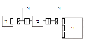
*1 |
Seat Position Sensor (Separate Type Front Seat Cushion Spring Assembly LH) |
*2 |
Front Seat Inner Belt Assembly LH |
|
*3 |
Airbag Sensor Assembly |
*4 |
Wire Harness |
|
*a |
Front view of wire harness connector (to Seat Position Sensor (Separate Type Front Seat Cushion Spring Assembly LH)) |
- |
- |
Standard Resistance:
|
Tester Connection |
Condition |
Specified Condition |
|---|---|---|
|
q10-2 (VS) - Body ground |
Always |
1 MΩ or higher |
|
q10-1 (GND) - Body ground |
Always |
1 MΩ or higher |
| NG |
|
REPAIR OR REPLACE HARNESS OR CONNECTOR |
|
|
71. |
CHECK HARNESS AND CONNECTOR (FRONT SEAT INNER BELT ASSEMBLY LH - AIRBAG SENSOR ASSEMBLY) |
(a) Measure the resistance according to the value(s) in the table below.
|
*1 |
Seat Position Sensor (Separate Type Front Seat Cushion Spring Assembly LH) |
*2 |
Front Seat Inner Belt Assembly LH |
|
*3 |
Airbag Sensor Assembly |
*4 |
Wire Harness |
|
*a |
Front view of wire harness connector (to Front Seat Inner Belt Assembly LH) |
- |
- |
Standard Resistance:
|
Tester Connection |
Condition |
Specified Condition |
|---|---|---|
|
O23-4 (LSP+) - Body ground |
Always |
1 MΩ or higher |
|
O23-3 (LSP-) - Body ground |
Always |
1 MΩ or higher |
| OK |
|
| NG |
|
REPAIR OR REPLACE HARNESS OR CONNECTOR |
|
72. |
CHECK CONNECTION OF CONNECTORS |
(a) Check that the connectors are properly connected to the front seat inner belt assembly LH.
OK:
The connectors are properly connected.
| NG |
|
CONNECT CONNECTORS PROPERLY |
|
|
73. |
CHECK CONNECTORS |
Pre-procedure1
|
(a) Disconnect the front seat inner belt assembly LH connector. |
|
Procedure1
(b) Check that the terminals of the connectors are not deformed or damaged.
OK:
The terminals are not deformed or damaged.
Post-procedure1
(c) None
| NG |
|
REPLACE FRONT SEAT INNER BELT ASSEMBLY LH OR REPAIR OR REPLACE HARNESS OR CONNECTOR |
|
|
74. |
CHECK HARNESS AND CONNECTOR (SEAT POSITION SENSOR - FRONT SEAT INNER BELT ASSEMBLY LH) |
Pre-procedure1
(a) Using a service wire, connect terminals 2 (LSP+) and 1 (LSP-) of connector F.
NOTICE:
Do not forcibly insert the service wire into the terminals of the connector when connecting a service wire.
Procedure1
(b) Measure the resistance according to the value(s) in the table below.
|
*1 |
Seat Position Sensor (Separate Type Front Seat Cushion Spring Assembly LH) |
*2 |
Front Seat Inner Belt Assembly LH |
|
*3 |
Airbag Sensor Assembly |
*4 |
Wire Harness |
|
*5 |
Service Wire |
- |
- |
|
*a |
Front view of wire harness connector (to Seat Position Sensor (Separate Type Front Seat Cushion Spring Assembly LH)) |
*b |
Front view of wire harness connector (to Front Seat Inner Belt Assembly LH) |
Standard Resistance:
|
Tester Connection |
Condition |
Specified Condition |
|---|---|---|
|
q10-2 (VS) - q10-1 (GND) |
Always |
Below 1 Ω |
Post-procedure1
(c) Disconnect the service wire from connector F.
| NG |
|
REPAIR OR REPLACE HARNESS OR CONNECTOR |
|
|
75. |
CHECK HARNESS AND CONNECTOR (FRONT SEAT INNER BELT ASSEMBLY LH - AIRBAG SENSOR ASSEMBLY) |
Pre-procedure1
(a) Using a service wire, connect terminals 27 (LSP+) and 24 (GNDL) of connector B.
NOTICE:
Do not forcibly insert the service wire into the terminals of the connector when connecting a service wire.
Procedure1
(b) Measure the resistance according to the value(s) in the table below.
|
*1 |
Seat Position Sensor (Separate Type Front Seat Cushion Spring Assembly LH) |
*2 |
Front Seat Inner Belt Assembly LH |
|
*3 |
Airbag Sensor Assembly |
*4 |
Wire Harness |
|
*5 |
Service Wire |
- |
- |
|
*a |
Front view of wire harness connector (to Front Seat Inner Belt Assembly LH) |
*b |
Front view of wire harness connector (to Airbag Sensor Assembly) |
Standard Resistance:
|
Tester Connection |
Condition |
Specified Condition |
|---|---|---|
|
O23-4 (LSP+) - O23-3 (LSP-) |
Always |
Below 1 Ω |
Post-procedure1
(c) Disconnect the service wire from connector B.
| OK |
|
| NG |
|
REPAIR OR REPLACE HARNESS OR CONNECTOR |
|
|
|