| Last Modified: 05-13-2024 | 6.11:8.1.0 | Doc ID: RM1000000027FLU |
| Model Year Start: 2023 | Model: Corolla | Prod Date Range: [09/2022 - ] |
| Title: HEATING / AIR CONDITIONING: COMPRESSOR (for 2ZR-FXE): INSTALLATION; 2023 - 2025 MY Corolla Corolla HV [09/2022 - ] | ||
INSTALLATION
PROCEDURE
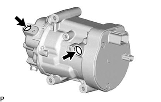
1. ADJUST COMPRESSOR OIL
|
(a) When replacing the compressor with motor assembly with a new one, gradually discharge the inert gas from the service valve, and drain the following amount of oil from the new compressor with motor assembly before installation. Standard: (Oil capacity inside the new compressor with motor assembly: 110 to 125 cc (3.73 to 4.22 fl. oz)) - (Remaining oil amount in the removed compressor with motor assembly) = (Oil amount to be removed from the new compressor) NOTICE:
|
|
2. INSTALL COMPRESSOR WITH MOTOR ASSEMBLY
|
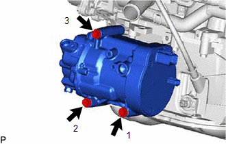
(a) Install the compressor with motor assembly with the 3 bolts. Torque: 25 N·m {255 kgf·cm, 18 ft·lbf} HINT: Tighten the bolts in the order shown in the illustration. |
|
(b) Install the bracket with the bolt.
Torque:
8.0 N·m {82 kgf·cm, 71 in·lbf}
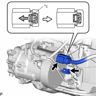
(c) Connect the connector (B).

|
*a |
Connector (A) |
|
*b |
Connector (B) |
|
*c |
Green-colored Lock |

|
Slide |
(d) Remove the insulating tape from the connector (A).
(e) Connect the connector (A) and slide the green-colored lock as shown in the illustration to securely lock it.
CAUTION:
Make sure to wear insulated gloves.
NOTICE:
Make sure that the connector is connected securely.
3. CONNECT SUCTION HOSE SUB-ASSEMBLY
(a) Remove the vinyl tape from the suction hose sub-assembly.
(b) Sufficiently apply compressor oil to a new O-ring and the fitting surface of the compressor with motor assembly.
Compressor Oil:
ND-OIL 11 or equivalent
(c) Install the O-ring to the suction hose sub-assembly.
NOTICE:
Keep the O-ring and O-ring fitting surface free of foreign matter.
(d) Connect the suction hose sub-assembly to the compressor with motor assembly with the bolt.
Torque:
9.8 N·m {100 kgf·cm, 87 in·lbf}
4. CONNECT DISCHARGE HOSE SUB-ASSEMBLY
(a) Remove the vinyl tape from the discharge hose sub-assembly.
(b) Sufficiently apply compressor oil to a new O-ring and the fitting surface of the compressor with motor assembly.
Compressor Oil:
ND-OIL 11 or equivalent
(c) Install the O-ring to the discharge hose sub-assembly.
NOTICE:
Keep the O-ring and O-ring fitting surface free of foreign matter.
(d) Connect the discharge hose sub-assembly to the compressor with motor assembly with the bolt.
Torque:
9.8 N·m {100 kgf·cm, 87 in·lbf}
5. INSTALL NO. 1 AIR CLEANER INLET
6. INSTALL AIR CLEANER SUPPORT BRACKET ASSEMBLY
7. INSTALL AIR CLEANER CASE SUB-ASSEMBLY
8. INSTALL AIR CLEANER FILTER ELEMENT SUB-ASSEMBLY
9. INSTALL AIR CLEANER HOSE ASSEMBLY
10. INSTALL AIR CLEANER CAP SUB-ASSEMBLY
11. INSTALL NO. 2 AIR CLEANER INLET
12. INSTALL RADIATOR SUPPORT OPENING COVER
13. INSTALL SERVICE PLUG GRIP
14. CHARGE AIR CONDITIONING SYSTEM WITH REFRIGERANT (for HFC-134a(R134a))
15. CHARGE AIR CONDITIONING SYSTEM WITH REFRIGERANT (for HFO-1234yf(R1234yf))
16. WARM UP COMPRESSOR (for HFC-134a(R134a))
17. WARM UP COMPRESSOR (for HFO-1234yf(R1234yf))
18. INSPECT FOR REFRIGERANT LEAK (for HFC-134a(R134a))
19. INSPECT FOR REFRIGERANT LEAK (for HFO-1234yf(R1234yf))
|
|
|


![2023 - 2025 MY Corolla Corolla HV [09/2022 - ]; 2ZR-FXE (INTAKE / EXHAUST): INTAKE MANIFOLD: INSTALLATION+](/t3Portal/stylegraphics/info.gif)