| Last Modified: 05-13-2024 | 6.11:8.1.0 | Doc ID: RM1000000027APQ |
| Model Year Start: 2023 | Model: Corolla | Prod Date Range: [09/2022 - 11/2022] |
| Title: 2ZR-FAE (ENGINE CONTROL): SFI SYSTEM: ECM Power Source Circuit; 2023 MY Corolla [09/2022 - 11/2022] | ||
|
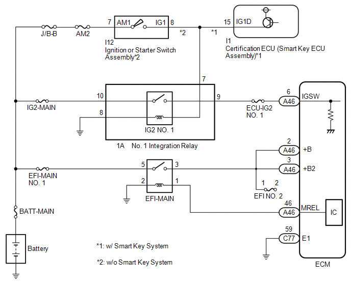
ECM Power Source Circuit |
DESCRIPTION
When the ignition switch is turned to ON, the battery voltage is applied to IGSW of the ECM. The output signal from the MREL terminal of the ECM causes a current to flow to the coil, closing the contacts of the EFI-MAIN relay and supplying power to either terminal +B or +B2 of the ECM.
WIRING DIAGRAM
CAUTION / NOTICE / HINT
NOTICE:
Inspect the fuses for circuits related to this system before performing the following procedure.
PROCEDURE
|
1. |
CHECK HARNESS AND CONNECTOR (ECM - BODY GROUND) |
(a) Disconnect the ECM connector.
(b) Measure the resistance according to the value(s) in the table below.
Standard Resistance:
|
Tester Connection |
Condition |
Specified Condition |
|---|---|---|
|
C77-59 (E1) - Body ground |
Always |
Below 1 Ω |
| NG |

|
REPAIR OR REPLACE HARNESS OR CONNECTOR |
|

|
2. |
CHECK TERMINAL VOLTAGE (IGSW TERMINAL VOLTAGE) |
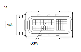
|
*a |
Front view of wire harness connector (to ECM) |
(a) Disconnect the ECM connector.
(b) Turn the ignition switch to ON.
(c) Measure the voltage according to the value(s) in the table below.
Standard Voltage:
|
Tester Connection |
Condition |
Specified Condition |
|---|---|---|
|
A46-6 (IGSW) - Body ground |
Ignition switch ON |
11 to 14 V |
| NG |
|
|
|
3. |
INSPECT EFI-MAIN RELAY |
(a) Inspect the EFI-MAIN relay.
Click here
![2020 - 2023 MY Corolla [01/2019 - 11/2022]; 2ZR-FAE (ENGINE CONTROL): RELAY: ON-VEHICLE INSPECTION+](/t3Portal/stylegraphics/info.gif)
| NG |
|
REPLACE EFI-MAIN RELAY |
|
|
4. |
CHECK HARNESS AND CONNECTOR (EFI-MAIN RELAY - BODY GROUND) |
(a) Remove the EFI-MAIN relay from the No. 1 engine room relay block and No. 1 junction block assembly.
(b) Measure the resistance according to the value(s) in the table below.
Standard Resistance:
|
Tester Connection |
Condition |
Specified Condition |
|---|---|---|
|
2 (EFI-MAIN relay) - Body ground |
Always |
Below 1 Ω |
| NG |
|
REPAIR OR REPLACE HARNESS OR CONNECTOR |
|
|
5. |
CHECK HARNESS AND CONNECTOR (EFI-MAIN RELAY - ECM) |
(a) Disconnect the ECM connector.
(b) Remove the EFI-MAIN relay from the No. 1 engine room relay block and No. 1 junction block assembly.
(c) Measure the resistance according to the value(s) in the table below.
Standard Resistance:
|
Tester Connection |
Condition |
Specified Condition |
|---|---|---|
|
1 (EFI-MAIN relay) - A46-46 (MREL) |
Always |
Below 1 Ω |
|
3 (EFI-MAIN relay) - A46-2 (+B) |
Always |
Below 1 Ω |
|
3 (EFI-MAIN relay) - A46-3 (+B2) |
Always |
Below 1 Ω |
|
1 (EFI-MAIN relay) or A46-46 (MREL) - Body ground and other terminals |
Always |
10 kΩ or higher |
|
3 (EFI-MAIN relay), A46-2 (+B) or A46-3 (+B2) - Body ground and other terminals |
Always |
10 kΩ or higher |
HINT:
If a short is detected in any of the above circuits, there may be a malfunction in the circuit of a connected ECU.
| NG |
|
REPAIR OR REPLACE HARNESS OR CONNECTOR |
|
|
6. |
CHECK TERMINAL VOLTAGE (POWER SOURCE OF EFI-MAIN RELAY) |
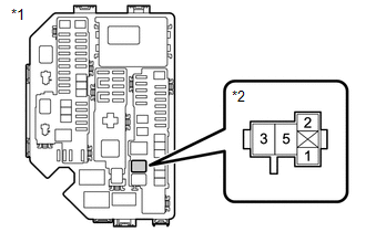
|
*1 |
NO. 1 Engine Room Relay Block and NO. 1 Junction Block Assembly |
|
*2 |
EFI-MAIN Relay |
(a) Remove the EFI-MAIN relay from the No. 1 engine room relay block and No. 1 junction block assembly.
(b) Measure the voltage according to the value(s) in the table below.
Standard Voltage:
|
Tester Connection |
Condition |
Specified Condition |
|---|---|---|
|
5 (EFI-MAIN relay) - Body ground |
Always |
11 to 14 V |
| OK |
|
PROCEED TO NEXT SUSPECTED AREA SHOWN IN PROBLEM SYMPTOMS TABLE |
| NG |
|
REPAIR OR REPLACE HARNESS OR CONNECTOR (BATTERY - EFI-MAIN RELAY) |
|
7. |
CHECK TERMINAL VOLTAGE (POWER SOURCE OF NO. 1 INTEGRATION RELAY) |
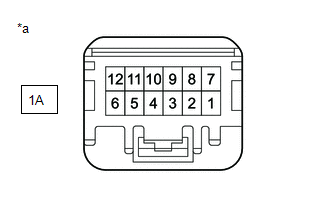
|
*a |
Front view of wire harness connector (to No. 1 Integration Relay) |
(a) Disconnect the No. 1 integration relay connector.
(b) Measure the voltage according to the value(s) in the table below.
Standard Voltage:
|
Tester Connection |
Condition |
Specified Condition |
|---|---|---|
|
1A-10 - Body ground |
Always |
11 to 14 V |
| NG |
|
REPAIR OR REPLACE HARNESS OR CONNECTOR (BATTERY - NO. 1 INTEGRATION RELAY) |
|
|
8. |
INSPECT NO. 1 INTEGRATION RELAY (IG2 NO. 1 RELAY) |
(a) Inspect the No. 1 integration relay (IG2 NO. 1 relay).
Click here
| NG |
|
|
|
9. |
CHECK HARNESS AND CONNECTOR (NO. 1 INTEGRATION RELAY - ECM) |
(a) Disconnect the No. 1 integration relay connector.
(b) Disconnect the ECM connector.
(c) Measure the resistance according to the value(s) in the table below.
Standard Resistance:
|
Tester Connection |
Condition |
Specified Condition |
|---|---|---|
|
1A-9 - A46-6 (IGSW) |
Always |
Below 1 Ω |
|
1A-9 or A46-6 (IGSW) - Body ground and other terminals |
Always |
10 kΩ or higher |
HINT:
If a short is detected in any of the above circuits, there may be a malfunction in the circuit of a connected ECU.
| NG |
|
REPAIR OR REPLACE HARNESS OR CONNECTOR |
|
|
10. |
CHECK HARNESS AND CONNECTOR (NO. 1 INTEGRATION RELAY - BODY GROUND) |
(a) Disconnect the No. 1 integration relay connector.
(b) Measure the resistance according to the value(s) in the table below.
Standard Resistance:
|
Tester Connection |
Condition |
Specified Condition |
|---|---|---|
|
1A-8 - Body ground |
Always |
Below 1 Ω |
|
Result |
Proceed to |
|---|---|
|
OK (w/ Smart Key System) |
A |
|
OK (w/o Smart Key System) |
B |
|
NG |
C |
| B |
|
| C |
|
REPAIR OR REPLACE HARNESS OR CONNECTOR |
|
|
11. |
CHECK HARNESS AND CONNECTOR (CERTIFICATION ECU (SMART KEY ECU ASSEMBLY) - NO. 1 INTEGRATION RELAY) |
(a) Disconnect the certification ECU (smart key ECU assembly) connector.
(b) Disconnect the No. 1 integration relay connector.
(c) Disconnect the instrument panel junction block assembly 4F connector.
HINT:
Disconnect the IG1-NO. 1, IG1-NO. 2 and IG2-NO. 2 relays connected between the checked terminals as the coil inside the relay influences the measurement value.
(d) Measure the resistance according to the value(s) in the table below.
Standard Resistance:
|
Tester Connection |
Condition |
Specified Condition |
|---|---|---|
|
I1-15 (IG1D) - 1A-7 |
Always |
Below 1 Ω |
|
I1-15 (IG1D) or 1A-7 - Body ground and other terminals |
Always |
10 kΩ or higher |
| OK |
|
| NG |
|
REPAIR OR REPLACE HARNESS OR CONNECTOR |
|
12. |
INSPECT IGNITION OR STARTER SWITCH ASSEMBLY |
(a) Inspect the ignition or starter switch assembly.
Click here
| NG |
|
|
|
13. |
CHECK HARNESS AND CONNECTOR (IGNITION OR STARTER SWITCH ASSEMBLY - NO. 1 INTEGRATION RELAY) |
(a) Disconnect the ignition or starter switch assembly connector.
(b) Disconnect the No. 1 integration relay connector.
(c) Disconnect the instrument panel junction block assembly 4F connector.
HINT:
Disconnect the IG1-NO. 1, IG1-NO. 2 and IG2-NO. 2 relays connected between the checked terminals as the coil inside the relay influences the measurement value.
(d) Measure the resistance according to the value(s) in the table below.
Standard Resistance:
|
Tester Connection |
Condition |
Specified Condition |
|---|---|---|
|
I12-8 (IG1) - 1A-7 |
Always |
Below 1 Ω |
|
I12-8 (IG1) or 1A-7 - Body ground and other terminals |
Always |
10 kΩ or higher |
| OK |
|
REPAIR OR REPLACE HARNESS OR CONNECTOR (BATTERY - IGNITION OR STARTER SWITCH ASSEMBLY) |
| NG |
|
REPAIR OR REPLACE HARNESS OR CONNECTOR |
|
|
|