- Perform "Reset Memory"
- Perform "Calibration"
| Last Modified: 05-13-2024 | 6.11:8.1.0 | Doc ID: RM10000000277VD |
| Model Year Start: 2023 | Model: Corolla | Prod Date Range: [09/2022 - ] |
| Title: HYBRID / BATTERY CONTROL: FRAME WIRE: REMOVAL; 2023 - 2025 MY Corolla Corolla HV [09/2022 - ] | ||
REMOVAL
CAUTION / NOTICE / HINT
The necessary procedures (adjustment, calibration, initialization or registration) that must be performed after parts are removed and installed, or replaced during HV floor under wire removal/installation are shown below.
Necessary Procedures After Parts Removed/Installed/Replaced
|
Replaced Part or Performed Procedure |
Necessary Procedure |
Effect/Inoperative Function when Necessary Procedure not Performed |
Link |
|---|---|---|---|
| *1: If matchmarks were not placed when removing parts related to steering operation, perform end position initial setting. | |||
|
Front wheel alignment adjustment |
|
|
|
|
End position initial setting |
- |
|
CAUTION:
NOTICE:
- After turning the power switch off, waiting time may be required before disconnecting the cable from the negative (-) auxiliary battery terminal.
- After turning the power switch off, waiting time may be required before disconnecting the cable from the negative (-) auxiliary battery terminal. Therefore, make sure to read the disconnecting the cable from the negative (-) auxiliary battery terminal notices before proceeding with work.
HINT:
When the cable is disconnected / reconnected to the auxiliary battery terminal, systems temporarily stop operating. However, each system has a function that completes learning the first time the system is used.
Learning completes when vehicle is driven
|
Effect/Inoperative Function when Necessary Procedure not Performed |
Necessary Procedure |
Link |
|---|---|---|
|
Front Camera System (for TMC Made) |
Drive the vehicle straight ahead at 15 km/h (9 mph) or more for 1 second or more. |
PROCEDURE
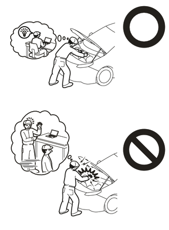
1. PRECAUTION
2. REMOVE SERVICE PLUG GRIP
3. REMOVE CONNECTOR COVER ASSEMBLY
4. CHECK TERMINAL VOLTAGE
5. TEMPORARILY INSTALL CONNECTOR COVER ASSEMBLY
6. DISCONNECT FLOOR UNDER WIRE
7. DISCONNECT REAR SEAT CENTER LAP TYPE BELT ASSEMBLY
8. REMOVE REAR SEAT CUSHION ASSEMBLY
9. REMOVE REAR SEAT CUSHION LOCK HOOK
10. REMOVE REAR DOOR SCUFF PLATE LH
11. REMOVE REAR UNDER SIDE COVER LH
12. REMOVE REAR DOOR SCUFF PLATE RH
HINT:
Use the same procedure as for the LH side.
13. REMOVE REAR UNDER SIDE COVER RH
HINT:
Use the same procedure as for the LH side.
14. REMOVE REAR UNDER COVER
15. REMOVE REAR SEAT CUSHION LEG SUB-ASSEMBLY
16. REMOVE NO. 1 HV BATTERY COVER PANEL RH
17. DISCONNECT FLOOR UNDER WIRE
18. REMOVE REAR FLOOR MAT ASSEMBLY (for AWD w/o Deck Board)
19. REMOVE DECK BOARD ASSEMBLY (for AWD w/ Deck Board)
20. REMOVE SPARE WHEEL CUSHION (for AWD)
21. REMOVE REAR NO. 1 FLOOR BOARD (for AWD w/ Deck Board)
22. REMOVE FRONT DECK FLOOR BOX (for AWD w/ Deck Board)
23. REMOVE REAR SEAT SIDE GARNISH RH (for AWD)
HINT:
Use the same procedure as for the LH side.
24. REMOVE REAR SEATBACK ASSEMBLY RH (for AWD)
25. REMOVE REAR FLOOR SIDE MEMBER COVER RH (w/ Cover)
26. REMOVE FRONT FLOOR COVER RH
HINT:
Perform the same procedure as for the front floor cover LH.
27. REMOVE FRONT SUSPENSION CROSSMEMBER SUB-ASSEMBLY
28. REMOVE FLOOR UNDER WIRE (for 2WD)
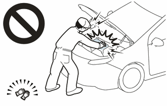
CAUTION:
Be sure to wear insulated gloves.
NOTICE:
Insulate the disconnected connectors with insulating tape.
|
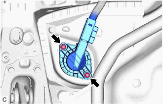
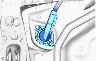
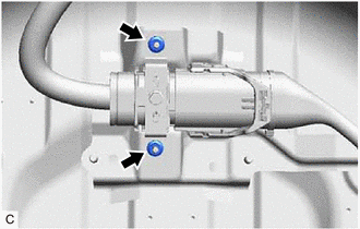
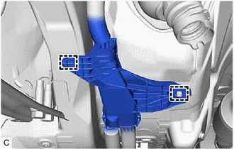
(a) Remove the 2 nuts. |
|
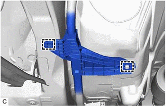
(b) Disengage the 4 clamps.
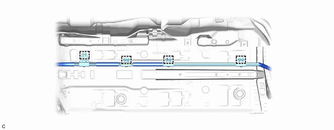
NOTICE:
If the clamps are removed forcibly, the stud bolts may be damaged.
|
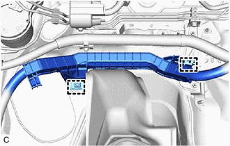
(c) Disengage the grommet and pull out the HV floor under wire from the floor panel hole. |
|
|
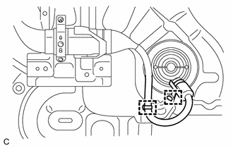
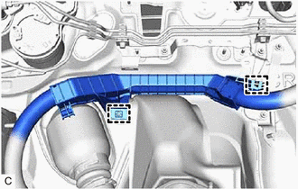
(d) Disengage the 2 clamps. |
|
|
(e) Disengage the 2 clamps to remove the HV floor under wire. |
|
29. REMOVE MOTOR CONNECTOR PROTECTOR (for AWD)
30. REMOVE FLOOR UNDER WIRE (for AWD)
CAUTION:
Be sure to wear insulated gloves.
NOTICE:
Insulate the disconnected connectors with insulating tape.
|
(a) Disengage the 2 clamps to disconnect the rear traction motor cable from the vehicle body. |
|
|
(b) Remove the 2 nuts to disconnect the radio earth bracket from the vehicle body. |
|
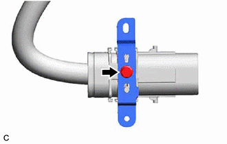
(c) Disconnect the rear traction motor cable connector.
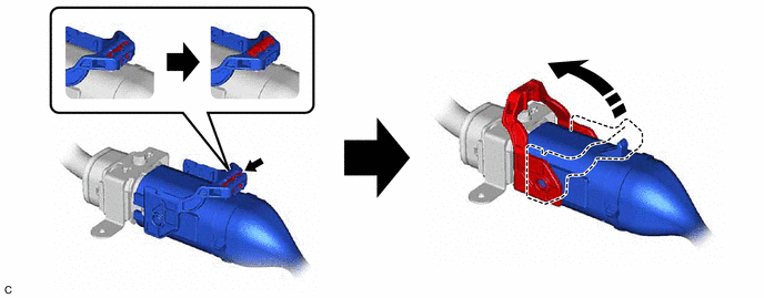
HINT:
Release the lock before rotating the lock lever.
|
(d) Remove the bolt and radio earth bracket from the HV floor under wire. |
|
|
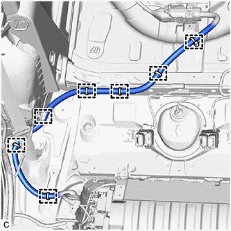
(e) Disengage the 7 clamps. |
|
|
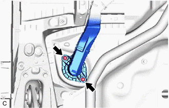
(f) Remove the 2 nuts. |
|
(g) Disengage the 4 clamps.
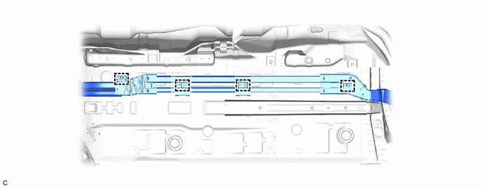
NOTICE:
If the clamps are removed forcibly, the stud bolts may be damaged.
|
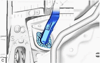
(h) Disengage the grommet and pull out the HV floor under wire from the floor panel hole. |
|
|
(i) Disengage the 2 clamps. |
|
|
(j) Disengage the 2 clamps to remove the HV floor under wire. |
|
|
|
|
![2023 - 2025 MY Corolla Corolla HV [09/2022 - ]; BRAKE CONTROL / DYNAMIC CONTROL SYSTEMS: ELECTRONICALLY CONTROLLED BRAKE SYSTEM (for HV Model): UTILITY](/t3Portal/stylegraphics/info.gif)
