- Reset memory
- Deceleration sensor zero point calibration
- CVT oil pressure calibration
| Last Modified: 05-13-2024 | 6.11:8.1.0 | Doc ID: RM10000000271KG |
| Model Year Start: 2023 | Model: Corolla | Prod Date Range: [09/2022 - 11/2022] |
| Title: 2ZR-FAE (ENGINE MECHANICAL): CAMSHAFT: REMOVAL; 2023 MY Corolla [09/2022 - 11/2022] | ||
REMOVAL
CAUTION / NOTICE / HINT
The necessary procedures (adjustment, calibration, initialization, or registration) that must be performed after parts are removed and installed, or replaced during camshaft removal/installation are shown below.
Necessary Procedures After Parts Removed/Installed/Replaced
|
Replaced Part or Performed Procedure |
Necessary Procedure |
Effect/Inoperative Function when Necessary Procedure not Performed |
Link |
|---|---|---|---|
|
*1: w/ Smart Key System
*2: w/o Smart Key System *3: w/ Steering Lock Function |
|||
|
Replacement of ECM |
Vehicle Identification Number (VIN) registration |
MIL comes on |
|
|
ECU communication ID registration (Immobiliser system) |
Engine start function |
||
|
|
|
||
|
Replacement of ECM*1 |
Code registration (Smart Key System (for Gasoline Model, Start Function)) |
|
|
|
Replacement of ECM*2 |
Code registration (Immobiliser system) |
|
|
|
Inspection After Repair |
|
|
|
Front wheel alignment adjustment |
|
|
|
|
CVT fluid |
ATF thermal degradation estimate reset |
The value of the Data List item "ATF Thermal Degradation Estimate" is not estimated correctly |
|
HINT:
When the cable is disconnected / reconnected to the battery terminal, systems temporarily stop operating. However, each system has a function that completes learning the first time the system is used.
Learning completes when vehicle is driven
|
Effect/Inoperative Function when Necessary Procedure not Performed |
Necessary Procedure |
Link |
|---|---|---|
|
Pre-collision System (for TMMMS Made) |
Drive the vehicle straight ahead at 35 km/h (22 mph) or more for 5 seconds or more. |
|
|
Lane Tracing Assist System (for TMMMS Made) |
||
|
Lane Departure Alert System (for TMMMS Made) |
PROCEDURE
1. REMOVE CHAIN SUB-ASSEMBLY
2. INSPECT CAMSHAFT TIMING GEAR ASSEMBLY
3. INSPECT CAMSHAFT TIMING EXHAUST GEAR ASSEMBLY
4. REMOVE CAMSHAFT TIMING GEAR ASSEMBLY
5. REMOVE CAMSHAFT TIMING EXHAUST GEAR ASSEMBLY
6. REMOVE VALVE ROCKER ARM LOST MOTION DAMPER SUB-ASSEMBLY
|
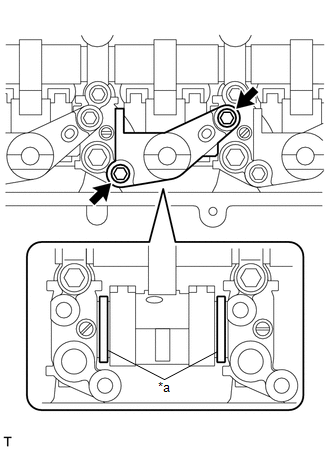
(a) Remove the 8 bolts and 4 valve rocker arm lost motion damper sub-assemblies. NOTICE:
|
|
7. INSTALL VALVE ROCKER ARM LOST MOTION DAMPER SUB-ASSEMBLY
|
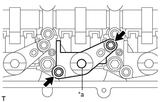
(a) Install the 4 valve rocker arm lost motion damper sub-assemblies with the 8 bolts. Uniformly tighten the bolts. Torque: 10 N·m {102 kgf·cm, 7 ft·lbf} |
|
(b) Add engine oil into the hole for engine oil.
8. REMOVE CAMSHAFT HOUSING SUB-ASSEMBLY
NOTICE:
- The camshaft housing sub-assembly is replaced with an assembled unit that includes the camshaft housing, camshafts, camshaft bearing caps, valve rocker shaft, continuously variable valve lift controller assembly and valve rocker arm lost motion damper sub-assembly. If disassembled, replace the camshaft housing sub-assembly.
-
The camshafts cannot be replaced by themselves.
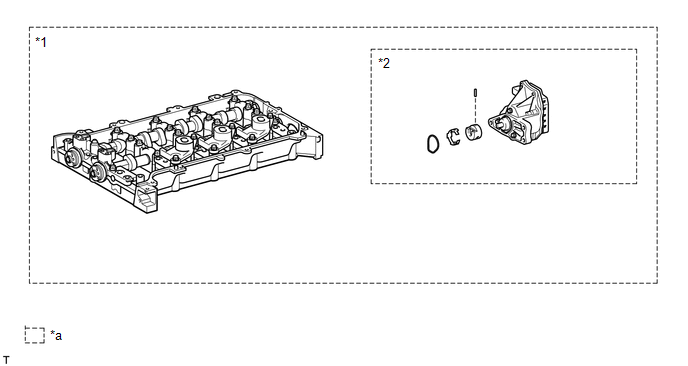
*1
Camshaft Housing Sub-assembly
*2
Continuously Variable Valve Lift Controller Assembly
*a
Set of parts that are replaced together
-
-
|
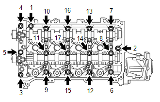
(a) Uniformly loosen and remove the 17 bearing cap bolts in the order shown in the illustration. NOTICE: Uniformly loosen the bearing cap bolts while keeping the camshaft housing level. |
|
|
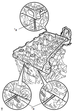
(b) Using a screwdriver, remove the camshaft housing sub-assembly by prying between the cylinder head sub-assembly and camshaft housing sub-assembly. NOTICE: Be careful not to damage the contact surfaces of the cylinder head sub-assembly and camshaft housing sub-assembly. HINT: Tape the screwdriver tip before use. |
|
9. REMOVE NO. 1 VALVE ROCKER ARM SUB-ASSEMBLY
10. REMOVE VALVE LASH ADJUSTER ASSEMBLY
11. INSPECT NO. 1 VALVE ROCKER ARM SUB-ASSEMBLY
12. INSPECT VALVE LASH ADJUSTER ASSEMBLY
|
|
|
![2020 - 2023 MY Corolla [01/2019 - 11/2022]; 2ZR-FAE (ENGINE CONTROL): SFI SYSTEM: REGISTRATION](/t3Portal/stylegraphics/info.gif)
