| Last Modified: 05-13-2024 | 6.11:8.1.0 | Doc ID: RM10000000271JC |
| Model Year Start: 2023 | Model: GR Corolla | Prod Date Range: [09/2022 - 11/2022] |
| Title: BRAKE CONTROL / DYNAMIC CONTROL SYSTEMS: ELECTRONICALLY CONTROLLED BRAKE SYSTEM (for Gasoline Model with Electric Parking Brake System TMC Made): C117B62; Brake Pressure Sensor "A" / Brake Switch "A" Signal Compare Failure; 2023 MY Corolla Corolla Hatchback GR Corolla [09/2022 - 11/2022] | ||
|
DTC |
C117B62 |
Brake Pressure Sensor "A" / Brake Switch "A" Signal Compare Failure |
DESCRIPTION
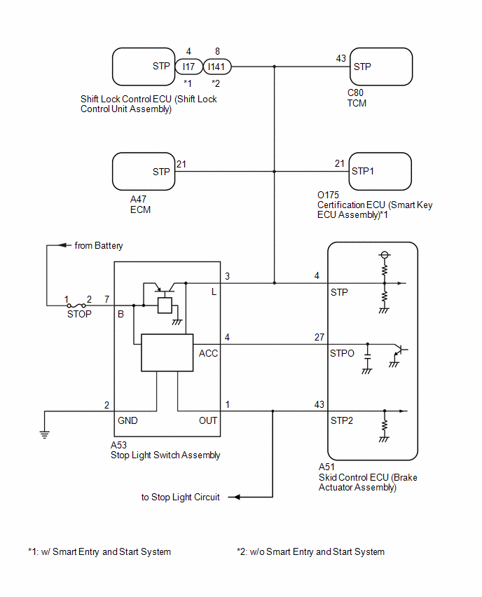
The skid control ECU (brake actuator assembly) receives stop light switch assembly signals and uses them to determine whether or not the brakes are applied.
When the brake pedal is depressed and no signal is received from the stop light switch assembly, this DTC is output.
|
DTC No. |
Detection Item |
DTC Detection Condition |
Trouble Area |
|---|---|---|---|
|
C117B62 |
Brake Pressure Sensor "A" / Brake Switch "A" Signal Compare Failure |
Either of the following is detected when the vehicle speed of 3 km/h (2 mph) or more:
|
|
WIRING DIAGRAM
CAUTION / NOTICE / HINT
NOTICE:
Inspect the fuses for circuits related to this system before performing the following procedure.
PROCEDURE
|
1. |
READ VALUE USING GTS (MASTER CYLINDER SENSOR) |
(a) Connect the GTS to the DLC3.
(b) Turn the ignition switch to ON.
(c) Enter the following menus: Chassis / Brake/EPB / Data List.
Chassis > Brake > Data List
|
Tester Display |
Measurement Item |
Range |
Normal Condition |
Diagnostic Note |
|---|---|---|---|---|
|
Master Cylinder Sensor 1 |
Master cylinder pressure sensor pressure (value detected by ECU) |
Min.: -1.00 MPa, Max.: 23.99 MPa |
Brake pedal released: -1.00 to 0.00 MPa |
Reading increases when brake pedal is depressed |
Chassis > Brake > Data List
|
Tester Display |
|---|
|
Master Cylinder Sensor 1 |
(d) Check the value of Data List item Master Cylinder Sensor 1 when the brake pedal is released.
OK:
The value of Data List item Master Cylinder Sensor 1 when the brake pedal is released is less than 0.15 MPa.
| NG |

|
|

|
2. |
CHECK HARNESS AND CONNECTOR (STOP LIGHT SWITCH ASSEMBLY SIGNAL INPUT CIRCUIT) |
|
(a) Make sure that there is no looseness at the locking part and the connecting part of the connector. OK: The connector is securely connected. |
|
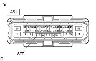
(b) Disconnect the A51 skid control ECU (brake actuator assembly) connector.
(c) Check both the connector case and the terminals for deformation and corrosion.
OK:
No deformation or corrosion.
(d) Measure the voltage according to the value(s) in the table below.
Standard Voltage:
|
Tester Connection |
Condition |
Specified Condition |
|---|---|---|
|
A51-4 (STP) - Body ground |
Brake pedal depressed |
11 to 14 V |
| OK |
|
|
|
3. |
CHECK HARNESS AND CONNECTOR (STOP LIGHT SWITCH ASSEMBLY - BRAKE ACTUATOR ASSEMBLY) |
(a) Make sure that there is no looseness at the locking part and the connecting part of the connector.
OK:
The connector is securely connected.
(b) Disconnect the A51 skid control ECU (brake actuator assembly) connector.
(c) Disconnect the A53 stop light switch assembly connector.
(d) Check both the connector case and the terminals for deformation and corrosion.
OK:
No deformation or corrosion.
(e) Measure the resistance according to the value(s) in the table below.
Standard Resistance:
|
Tester Connection |
Condition |
Specified Condition |
|---|---|---|
|
A53-3 (L) - A51-4 (STP) |
Always |
Below 1 Ω |
|
A53-3 (L) or A51-4 (STP) - Body ground and other terminals |
Always |
10 kΩ or higher |
| OK |
|
| NG |
|
REPAIR OR REPLACE HARNESS OR CONNECTOR |
|
4. |
CHECK DTC |
(a) Connect the GTS to the DLC3.
(b) Turn the ignition switch to ON.
(c) Read the DTCs following the prompts on the GTS. Enter the following menus: Chassis / Brake/EPB / Trouble Codes.
Chassis > Brake > Trouble Codes
(d) Check the details of the DTCs.
|
Result |
Proceed to |
|---|---|
|
C117B62 and C05401C, C054028 and/or C054049 are output simultaneously |
A |
|
C117B62 is output |
B |
| A |
|
| B |
|
GO TO BRAKE SYSTEM Inspect brake pedal free play: Click here
Inspect brake booster assembly: Click here
|
![2023 - 2025 MY Corolla Corolla Hatchback GR Corolla [09/2022 - ]; BRAKE SYSTEM (OTHER): BRAKE PEDAL (for Gasoline Model): ADJUSTMENT](/t3Portal/stylegraphics/info.gif)
|
|
|