- Wireless Door Lock Control System (for Gasoline Model with Smart Key System)
- Smart Key System (for Gasoline Model, Entry Function)
- Smart Key System (for Gasoline Model, Start Function)
- Steering lock function*3
| Last Modified: 05-13-2024 | 6.11:8.1.0 | Doc ID: RM100000002714H |
| Model Year Start: 2023 | Model: Corolla Hatchback | Prod Date Range: [09/2022 - 11/2022] |
| Title: EG60 (MANUAL TRANSMISSION / TRANSAXLE): TRANSMISSION CONTROL CABLE (except TMC Made): ADJUSTMENT; 2023 MY Corolla Corolla Hatchback [09/2022 - 11/2022] | ||
ADJUSTMENT
CAUTION / NOTICE / HINT
The necessary procedures (adjustment, calibration, initialization or registration) that must be performed after parts are removed and installed, or replaced during transmission control cable assembly adjustment are shown below.
Necessary Procedures After Parts Removed/Installed/Replaced
|
Replaced Part or Performed Procedure |
Necessary Procedure |
Effect/Inoperative Function when Necessary Procedure not Performed |
Link |
|---|---|---|---|
|
*1: w/ Smart Key System
*2: w/o Smart Key System *3: w/ Steering Lock Function |
|||
|
Replacement of ECM |
Vehicle Identification Number (VIN) registration |
MIL comes on |
|
|
ECU communication ID registration (Immobiliser system) |
Engine start function |
||
|
Replacement of ECM*1 |
Code registration (Smart Key System (for Gasoline Model, Start Function)) |
|
|
|
Replacement of ECM*2 |
Code registration (Immobiliser system) |
|
|
HINT:
When the cable is disconnected / reconnected to the battery terminal, systems temporarily stop operating. However, each system has a function that completes learning the first time the system is used.
Learning completes when vehicle is driven
|
Effect/Inoperative Function when Necessary Procedure not Performed |
Necessary Procedure |
Link |
|---|---|---|
|
Pre-collision System (for TMMMS Made) |
Drive the vehicle straight ahead at 35 km/h (22 mph) or more for 5 seconds or more. |
|
|
Lane Tracing Assist System (for TMMMS Made) |
||
|
Lane Departure Alert System (for TMMMS Made) |
PROCEDURE
1. SECURE VEHICLE
(a) Fully apply the parking brake and chock a wheel.
CAUTION:
-
Make sure to apply the parking brake and chock a wheel before performing this procedure.
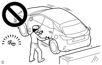
- If the vehicle is not secure and the shift lever is moved to neutral, the vehicle may suddenly move, possibly resulting in an accident or serious injury.
2. PRECAUTION
NOTICE:
After turning the ignition switch off, waiting time may be required before disconnecting the cable from the negative (-) battery terminal.
3. DISCONNECT CABLE FROM NEGATIVE BATTERY TERMINAL
4. REMOVE BATTERY
5. REMOVE CONSOLE BOX ASSEMBLY
6. REMOVE RADIATOR SUPPORT OPENING COVER
7. REMOVE INLET NO. 1 AIR CLEANER
8. REMOVE AIR CLEANER CAP WITH AIR CLEANER HOSE
9. REMOVE AIR CLEANER FILTER ELEMENT SUB-ASSEMBLY
10. REMOVE AIR CLEANER CASE SUB-ASSEMBLY
11. REMOVE ECM
12. REMOVE BATTERY CLAMP SUB-ASSEMBLY
13. ADJUST TRANSMISSION CONTROL CABLE ASSEMBLY
HINT:
- After the floor shift shift lever assembly or the transmission control cable assembly is replaced, be sure to adjust the transmission control cable assembly.
- If the shift lever does not move (or the shift lever is difficult to move) to the 1st or 2nd position, or if it is possible to move the shift lever to the reverse position without pulling up the slider shaft, the length of the transmission control cable assembly must be adjusted.
|
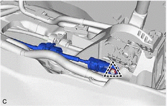
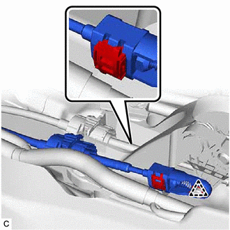
(a) Remove the clip and disconnect the transmission control select cable from the floor shift shift lever assembly. |
|
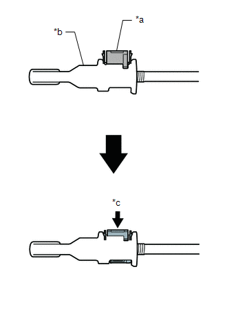
(b) Push the 2 claws together at the top of the lock piece. While holding the 2 claws together, push the 2 lugs on the bottom of the lock piece toward each other and upward to push up the lock piece.
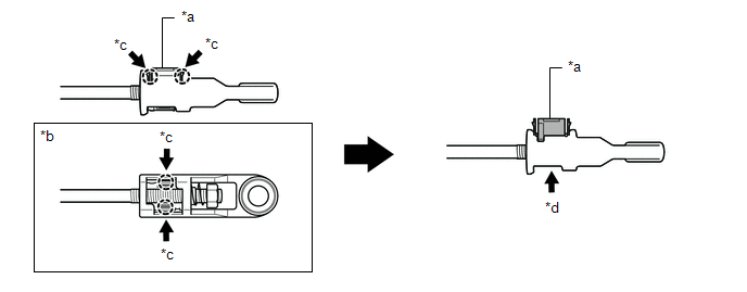
|
*a |
Lock Piece |
*b |
Bottom View |
|
*c |
Push |
*d |
Push up |
|
(c) Connect the transmission control select cable to the floor shift shift lever assembly and install the clip. NOTICE:
|
|
|
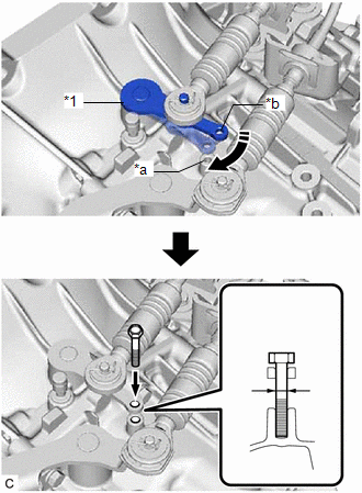
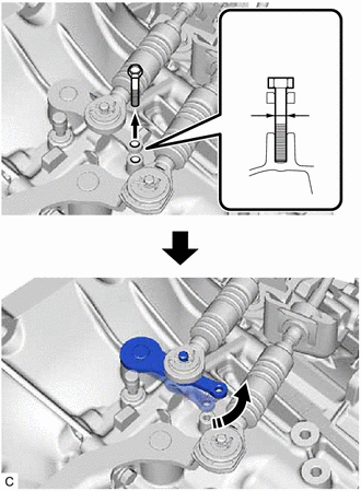
(d) Align the hole of the outer select lever with the hole in the manual transmission case. |
|
(e) Insert a bolt into the aligned holes to secure the outer select lever in place.
NOTICE:
Do not push in the bolt forcefully or damage the front transaxle case.
HINT:
- Use a bolt with a diameter of 6 mm (0.236 in.) and a length of at least 36 mm (1.42 in.).
- Depending on the bolt diameter, it may be difficult to insert the bolt. In that case, use a bolt with a diameter smaller than 6 mm (0.236 in.).
|
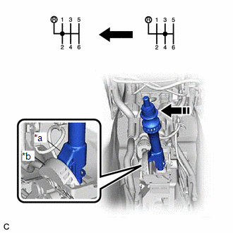
(f) Push the slider shaft against the cam wall. NOTICE:
|
|
|
(g) Push the lock piece into the adjuster case. NOTICE:
|
|
|
(h) Remove the bolt to release the select outer lever. |
|
14. INSTALL BATTERY CLAMP SUB-ASSEMBLY
15. INSTALL ECM
16. INSTALL AIR CLEANER CASE SUB-ASSEMBLY
17. INSTALL AIR CLEANER FILTER ELEMENT SUB-ASSEMBLY
18. INSTALL AIR CLEANER CAP WITH AIR CLEANER HOSE
19. INSTALL INLET NO. 1 AIR CLEANER
20. INSTALL RADIATOR SUPPORT OPENING COVER
21. INSTALL CONSOLE BOX ASSEMBLY
22. INSTALL BATTERY
23. CONNECT CABLE TO NEGATIVE BATTERY TERMINAL
24. INITIALIZATION AFTER RECONNECTING BATTERY TERMINAL
HINT:
When disconnecting and reconnecting the battery, there is an automatic learning function that completes learning when the respective system is used.
|
|
|
![2019 - 2025 MY Corolla Corolla Hatchback [06/2018 - ]; M20A-FKS (ENGINE CONTROL): SFI SYSTEM: REGISTRATION](/t3Portal/stylegraphics/info.gif)
