| Last Modified: 05-13-2024 | 6.11:8.1.0 | Doc ID: RM10000000270A7 |
| Model Year Start: 2023 | Model: GR Corolla | Prod Date Range: [09/2022 - 11/2022] |
| Title: NETWORKING: CXPI COMMUNICATION SYSTEM: B235587,B235787-B235987; Power Distribution Box Missing Message; 2023 MY Corolla Corolla Hatchback Corolla HV GR Corolla [09/2022 - 11/2022] | ||
|
DTC |
B235587 |
Power Distribution Box Missing Message |
|
DTC |
B235787 |
Wiper Module Missing Message |
|
DTC |
B235887 |
Smart LDM Left Missing Message |
|
DTC |
B235987 |
Smart LDM Right Missing Message |
DESCRIPTION
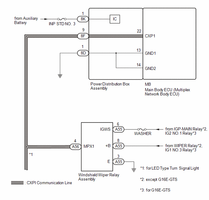
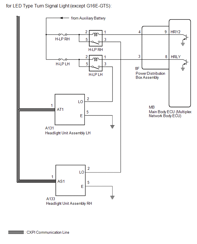
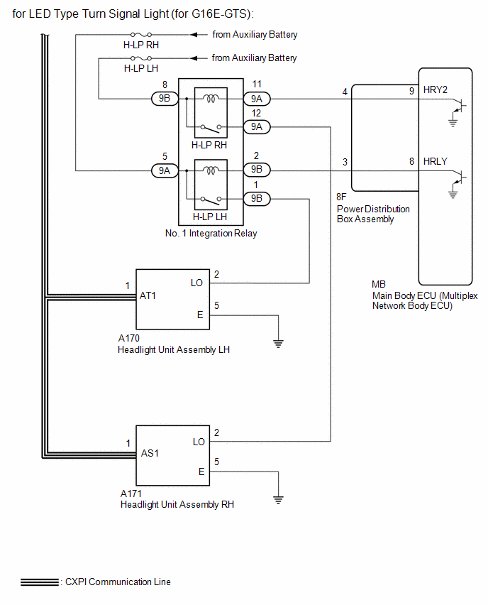
This DTC is stored when CXPI communication between the power distribution box assembly, windshield wiper relay assembly, headlight unit assembly LH* or headlight unit assembly RH* and main body ECU (multiplex network body ECU) stops for 10 seconds or more.
- *: for LED Type Turn Signal Light
|
DTC No. |
Detection Item |
DTC Detection Condition |
Trouble Area |
DTC Output from |
|---|---|---|---|---|
|
B235587 |
Power Distribution Box Missing Message |
No communication between power distribution box assembly and main body ECU (multiplex network body ECU) for 10 seconds or more |
|
Main Body |
|
B235787 |
Wiper Module Missing Message |
No communication between windshield wiper relay assembly and main body ECU (multiplex network body ECU) for 10 seconds or more |
|
Main Body |
|
B235887 |
Smart LDM Left Missing Message |
No communication between headlight unit assembly LH and main body ECU (multiplex network body ECU) for 10 seconds or more* |
|
Main Body |
|
B235987 |
Smart LDM Right Missing Message |
No communication between headlight unit assembly RH and main body ECU (multiplex network body ECU) for 10 seconds or more* |
|
Main Body |
- *: for LED Type Turn Signal Light
WIRING DIAGRAM
CAUTION / NOTICE / HINT
NOTICE:
- Inspect the fuses for circuits related to this system before performing the following procedure.
- Do not remove or install the power distribution box assembly with the negative (-) auxiliary battery terminal connected.
- When using the GTS with the ignition switch off, connect the GTS to the DLC3 and turn a courtesy light switch on and off at intervals of 1.5 seconds or less until communication between the GTS and the vehicle begins. Then select Model Code "KEY REGIST" under manual mode and enter the following menus: Body Electrical / Smart Key. While using the GTS, periodically turn a courtesy light switch on and off at intervals of 1.5 seconds or less to maintain communication between the GTS and the vehicle.
-
If the main body ECU (multiplex network body ECU) is replaced, refer to Registration.
for HV Model: Click here
![2023 - 2025 MY Corolla Corolla HV [09/2022 - ]; THEFT DETERRENT / KEYLESS ENTRY: SMART KEY SYSTEM (for Start Function, HV Model): REGISTRATION](/t3Portal/stylegraphics/info.gif)
for Gasoline Model, except TMMMS Made: Click here
-
After the ignition switch is turned off, there may be a waiting time before disconnecting the negative (-) auxiliary battery terminal.
Click here
HINT:
When disconnecting and reconnecting the auxiliary battery, there is an automatic learning function that completes learning when the respective system is used.
Click here
PROCEDURE
|
1. |
CLEAR DTC |
(a) Clear the DTCs.
Body Electrical > Main Body > Clear DTCs
|

|
2. |
CHECK FOR DTC |
(a) Check for DTCs.
Body Electrical > Main Body > Trouble Codes
|
Result |
Proceed to |
|---|---|
|
B235587, B235787, B235887* and B235987* are output |
A |
|
B235787, B235887 and B235987 are output* |
B |
|
DTC B235587 is output |
C |
|
DTC B235787 is output |
D |
|
DTC B235887* is output |
E |
|
DTC B235987* is output |
F |
|
DTC is not output |
G |
| B |

|
| C |
|
| D |
|
| E |
|
| F |
|
| G |
|
|
|
3. |
INSPECT POWER DISTRIBUTION BOX ASSEMBLY |
|
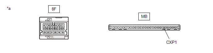
*a |
Component without harness connected (Power Distribution Box Assembly) |
- |
- |
(a) Remove the power distribution box assembly.
Click here
(b) Remove the main body ECU (multiplex network body ECU) from the power distribution box assembly.
(c) Disconnect the 8F power distribution box assembly connector.
(d) Measure the resistance according to the value(s) in the table below.
Standard Resistance
|
Tester Connection |
Condition |
Specified Condition |
|---|---|---|
|
MB-22 (CXP1) - 8F-9 |
Always |
Below 1 Ω |
| OK |
|
| NG |
|
|
4. |
CHECK HARNESS AND CONNECTOR (POWER DISTRIBUTION BOX ASSEMBLY - WINDSHIELD WIPER RELAY ASSEMBLY) |
(a) Disconnect the cable from the negative (-) auxiliary battery terminal.
(b) Disconnect the 8F power distribution box assembly connector.
(c) Disconnect the A56 windshield wiper relay assembly connector.
(d) Disconnect the A133*2 or A171*3 headlight unit assembly RH connector.*1
(e) Disconnect the A131*2 or A170*3 headlight unit assembly LH connector.*1
-
*1: for LED Type Turn Signal Light
*2: except G16E-GTS
*3: for G16E-GTS
(f) Measure the resistance according to the value(s) in the table below.
Standard Resistance:
|
Tester Connection |
Condition |
Specified Condition |
|---|---|---|
|
8F-9 - A56-4 (MPX1) |
Cable disconnected from negative (-) auxiliary battery terminal |
Below 1 Ω |
|
8F-9 or A56-4 (MPX1) - Body ground |
Cable disconnected from negative (-) auxiliary battery terminal |
10 kΩ or higher |
| OK |
|
| NG |
|
REPAIR OR REPLACE HARNESS OR CONNECTOR |
|
5. |
CHECK HARNESS AND CONNECTOR (POWER DISTRIBUTION BOX ASSEMBLY - POWER SOURCE AND BODY GROUND) |
(a) Disconnect the 8D or 8K power distribution box assembly connector.
(b) Measure the voltage according to the value(s) in the table below.
Standard Voltage:
|
Tester Connection |
Condition |
Specified Condition |
|---|---|---|
|
8K-1 - Body ground |
Always*1 Ignition switch off*2 |
11 to 14 V |
- *1: for Gasoline Model
- *2: for HEV Model
(c) Measure the resistance according to the value(s) in the table below.
Standard Resistance:
|
Tester Connection |
Condition |
Specified Condition |
|---|---|---|
|
8D-1 - Body ground |
Always |
Below 1 Ω |
| OK |
|
| NG |
|
REPAIR OR REPLACE HARNESS OR CONNECTOR |
|
6. |
CHECK HARNESS AND CONNECTOR (WINDSHIELD WIPER RELAY ASSEMBLY - POWER SOURCE AND BODY GROUND) |
(a) Disconnect the A55 windshield wiper relay assembly connector.
(b) Measure the voltage according to the value(s) in the table below.
Standard Voltage:
|
Tester Connection |
Condition |
Specified Condition |
|---|---|---|
|
A55-6 (IGWS) - Body ground |
Ignition switch ON |
11 to 14 V |
|
A55-8 (+B) - Body ground |
Ignition switch ON or less than approximately 60 seconds after ignition switch turned off |
11 to 14 V |
|
Approximately 60 seconds or more after ignition switch turned off |
(c) Measure the resistance according to the value(s) in the table below.
Standard Resistance:
|
Tester Connection |
Condition |
Specified Condition |
|---|---|---|
|
A55-3 (E) - Body ground |
Always |
Below 1 Ω |
| NG |
|
REPAIR OR REPLACE HARNESS OR CONNECTOR |
|
|
7. |
CHECK HARNESS AND CONNECTOR (WINDSHIELD WIPER RELAY ASSEMBLY - POWER DISTRIBUTION BOX ASSEMBLY) |
(a) Turn the ignition switch off.
(b) Disconnect the cable from the negative (-) auxiliary battery terminal.
(c) Disconnect the A56 windshield wiper relay assembly connector.
(d) Disconnect the 8F power distribution box assembly connector.
(e) Measure the resistance according to the value(s) in the table below.
Standard Resistance:
|
Tester Connection |
Condition |
Specified Condition |
|---|---|---|
|
A56-4 (MPX1) - 8F-9 |
Cable disconnected from negative (-) auxiliary battery terminal |
Below 1 Ω |
|
A56-4 (MPX1) or 8F-9 - Body ground |
Cable disconnected from negative (-) auxiliary battery terminal |
10 kΩ or higher |
| OK |
|
| NG |
|
REPAIR OR REPLACE HARNESS OR CONNECTOR |
|
8. |
CHECK HARNESS AND CONNECTOR (HEADLIGHT UNIT ASSEMBLY LH - POWER SOURCE AND BODY GROUND) |
(a) Disconnect the A131*1 or A170*2 headlight unit assembly LH connector.
(b) Measure the voltage according to the value(s) in the table below.
Standard Voltage:
|
Tester Connection |
Condition |
Specified Condition |
|---|---|---|
|
A131-2 (LO) - Body ground*1 |
Taillight on |
9.5 to 14 V |
|
Taillight off |
Below 1 V |
|
|
A170-2 (LO) - Body ground*2 |
Taillight on |
9.5 to 14 V |
|
Taillight off |
Below 1 V |
(c) Measure the resistance according to the value(s) in the table below.
Standard Resistance:
|
Tester Connection |
Condition |
Specified Condition |
|---|---|---|
|
A131-5 (E) - Body ground*1 |
Always |
Below 1 Ω |
|
A170-5 (E) - Body ground*2 |
Always |
Below 1 Ω |
-
*1: except G16E-GTS
*2: for G16E-GTS
|
Result |
Proceed to |
|---|---|
|
OK |
A |
|
NG (except G16E-GTS) |
B |
|
NG (for G16E-GTS) |
C |
| B |
|
| C |
|
|
|
9. |
CHECK HARNESS AND CONNECTOR (HEADLIGHT UNIT ASSEMBLY LH - POWER DISTRIBUTION BOX ASSEMBLY) |
(a) Turn the ignition switch off.
(b) Disconnect the cable from the negative (-) auxiliary battery terminal.
(c) Disconnect the 8F power distribution box assembly connector.
(d) Measure the resistance according to the value(s) in the table below.
Standard Resistance:
|
Tester Connection |
Condition |
Specified Condition |
|---|---|---|
|
A131-1 (AT1) - 8F-9*1 |
Cable disconnected from negative (-) auxiliary battery terminal |
Below 1 Ω |
|
A131-1 (AT1) or 8F-9 - Body ground*1 |
Cable disconnected from negative (-) auxiliary battery terminal |
10 kΩ or higher |
|
A170-1 (AT1) - 8F-9*2 |
Cable disconnected from negative (-) auxiliary battery terminal |
Below 1 Ω |
|
A170-1 (AT1) or 8F-9 - Body ground*2 |
Cable disconnected from negative (-) auxiliary battery terminal |
10 kΩ or higher |
-
*1: except G16E-GTS
*2: for G16E-GTS
| OK |
|
| NG |
|
REPAIR OR REPLACE HARNESS OR CONNECTOR |
|
10. |
INSPECT H-LP LH RELAY |
Click here
| NG |
|
REPLACE H-LP LH RELAY |
|
|
11. |
CHECK HARNESS AND CONNECTOR (H-LP LH RELAY - HEADLIGHT UNIT ASSEMBLY LH) |
(a) Measure the resistance according to the value(s) in the table below.
Standard Resistance:
|
Tester Connection |
Condition |
Specified Condition |
|---|---|---|
|
3 (H-LP LH relay) - A131-2 (LO)*1 |
Always |
Below 1 Ω |
|
3 (H-LP LH relay) or A131-2 (LO) - Body ground*1 |
Always |
10 kΩ or higher |
|
3 (H-LP LH relay) - A170-2 (LO)*2 |
Always |
Below 1 Ω |
|
3 (H-LP LH relay) or A170-2 (LO) - Body ground*2 |
Always |
10 kΩ or higher |
-
*1: except G16E-GTS
*2: for G16E-GTS
| NG |
|
REPAIR OR REPLACE HARNESS OR CONNECTOR |
|
|
12. |
CHECK HARNESS AND CONNECTOR (POWER SOURCE - H-LP LH RELAY) |
(a) Measure the voltage according to the value(s) in the table below.
Standard Voltage:
|
Tester Connection |
Condition |
Specified Condition |
|---|---|---|
|
2 (H-LP LH relay) - Body ground |
Always*1 Ignition switch off*2 |
11 to 14 V |
|
5 (H-LP LH relay) - Body ground |
Always*1 Ignition switch off*2 |
11 to 14 V |
- *1: for Gasoline Model
- *2: for HEV Model
| NG |
|
REPAIR OR REPLACE HARNESS OR CONNECTOR |
|
|
13. |
CHECK HARNESS AND CONNECTOR (H-LP LH RELAY - POWER DISTRIBUTION BOX ASSEMBLY) |
(a) Disconnect the 8F power distribution box assembly connector.
(b) Measure the resistance according to the value(s) in the table below.
Standard Resistance:
|
Tester Connection |
Condition |
Specified Condition |
|---|---|---|
|
1 (H-LP LH relay) - 8F-3 |
Always |
Below 1 Ω |
|
1 (H-LP LH relay) or 8F-3 - Body ground |
Always |
10 kΩ or higher |
| NG |
|
REPAIR OR REPLACE HARNESS OR CONNECTOR |
|
|
14. |
INSPECT POWER DISTRIBUTION BOX ASSEMBLY |
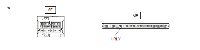
|
*a |
Component without harness connected (Power Distribution Box Assembly) |
- |
- |
(a) Remove the main body ECU (multiplex network body ECU) from the power distribution box assembly.
Click here
(b) Measure the resistance according to the value(s) in the table below.
Standard Resistance:
|
Tester Connection |
Condition |
Specified Condition |
|---|---|---|
|
8F-3 - MB-8 (HRLY) |
Always |
Below 1 Ω |
| OK |
|
| NG |
|
|
15. |
INSPECT NO. 1 INTEGRATION RELAY |
(a) Remove the No. 1 integration relay.
Click here
(b) Inspect the No. 1 integration relay.
Click here
| NG |
|
|
|
16. |
CHECK HARNESS AND CONNECTOR (NO. 1 INTEGRATION RELAY - HEADLIGHT UNIT ASSEMBLY LH) |
(a) Measure the resistance according to the value(s) in the table below.
Standard Resistance:
|
Tester Connection |
Condition |
Specified Condition |
|---|---|---|
|
9B-1 - A170-2 (LO) |
Always |
Below 1 Ω |
|
9B-1 or A170-2 (LO) - Body ground |
Always |
10 kΩ or higher |
| NG |
|
REPAIR OR REPLACE HARNESS OR CONNECTOR |
|
|
17. |
CHECK HARNESS AND CONNECTOR (POWER SOURCE - NO. 1 INTEGRATION RELAY) |
(a) Measure the voltage according to the value(s) in the table below.
Standard Voltage:
|
Tester Connection |
Condition |
Specified Condition |
|---|---|---|
|
9A-5 - Body ground |
Always*1 Ignition switch off*2 |
11 to 14 V |
- *1: for Gasoline Model
- *2: for HV Model
| NG |
|
REPAIR OR REPLACE HARNESS OR CONNECTOR |
|
|
18. |
CHECK HARNESS AND CONNECTOR (NO. 1 INTEGRATION RELAY - POWER DISTRIBUTION BOX ASSEMBLY) |
(a) Disconnect the 8F power distribution box assembly connector.
(b) Measure the resistance according to the value(s) in the table below.
Standard Resistance:
|
Tester Connection |
Condition |
Specified Condition |
|---|---|---|
|
9B-2 - 8F-3 |
Always |
Below 1 Ω |
|
9B-2 or 8F-3 - Body ground |
Always |
10 kΩ or higher |
| NG |
|
REPAIR OR REPLACE HARNESS OR CONNECTOR |
|
|
19. |
INSPECT POWER DISTRIBUTION BOX ASSEMBLY |
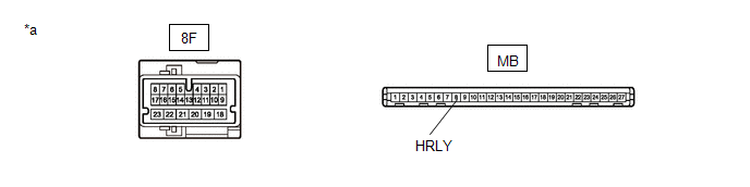
|
*a |
Component without harness connected (Power Distribution Box Assembly) |
- |
- |
(a) Remove the main body ECU (multiplex network body ECU) from the power distribution box assembly.
Click here
(b) Measure the resistance according to the value(s) in the table below.
Standard Resistance:
|
Tester Connection |
Condition |
Specified Condition |
|---|---|---|
|
8F-3 - MB-8 (HRLY) |
Always |
Below 1 Ω |
| OK |
|
| NG |
|
|
20. |
CHECK HARNESS AND CONNECTOR (HEADLIGHT UNIT ASSEMBLY RH - POWER SOURCE) |
(a) Disconnect the A133*1 or A171*2 headlight unit assembly RH connector.
(b) Measure the voltage according to the value(s) in the table below.
Standard Voltage:
|
Tester Connection |
Condition |
Specified Condition |
|---|---|---|
|
A133-2 (LO) - Body ground*1 |
Taillight on |
9.5 to 14 V |
|
Taillight off |
Below 1 V |
|
|
A171-2 (LO) - Body ground*2 |
Taillight on |
9.5 to 14 V |
|
Taillight off |
Below 1 V |
(c) Measure the resistance according to the value(s) in the table below.
Standard Resistance:
|
Tester Connection |
Condition |
Specified Condition |
|---|---|---|
|
A133-5 (E) - Body ground*1 |
Always |
Below 1 Ω |
|
A171-5 (E) - Body ground*2 |
Always |
Below 1 Ω |
-
*1: except G16E-GTS
*2: for G16E-GTS
|
Result |
Proceed to |
|---|---|
|
OK |
A |
|
NG (except G16E-GTS) |
B |
|
NG (for G16E-GTS) |
C |
| B |
|
| C |
|
|
|
21. |
CHECK HARNESS AND CONNECTOR (HEADLIGHT UNIT ASSEMBLY RH - POWER DISTRIBUTION BOX ASSEMBLY) |
(a) Turn the ignition switch off.
(b) Disconnect the cable from the negative (-) auxiliary battery terminal.
(c) Disconnect the 8F power distribution box assembly connector.
(d) Measure the resistance according to the value(s) in the table below.
Standard Resistance:
|
Tester Connection |
Condition |
Specified Condition |
|---|---|---|
|
A133-1 (AS1) - 8F-9*1 |
Cable disconnected from negative (-) auxiliary battery terminal |
Below 1 Ω |
|
A133-1 (AS1) or 8F-9 - Body ground*1 |
Cable disconnected from negative (-) auxiliary battery terminal |
10 kΩ or higher |
|
A171-1 (AS1) - 8F-9*2 |
Cable disconnected from negative (-) auxiliary battery terminal |
Below 1 Ω |
|
A171-1 (AS1) or 8F-9 - Body ground*2 |
Cable disconnected from negative (-) auxiliary battery terminal |
10 kΩ or higher |
-
*1: except G16E-GTS
*2: for G16E-GTS
| OK |
|
| NG |
|
REPAIR OR REPLACE HARNESS OR CONNECTOR |
|
22. |
INSPECT H-LP RH RELAY |
Click here
| NG |
|
REPLACE H-LP RH RELAY |
|
|
23. |
CHECK HARNESS AND CONNECTOR (H-LP RH RELAY - HEADLIGHT UNIT ASSEMBLY RH) |
(a) Measure the resistance according to the value(s) in the table below.
Standard Resistance:
|
Tester Connection |
Condition |
Specified Condition |
|---|---|---|
|
3 (H-LP RH relay) - A133-2 (LO)*1 |
Always |
Below 1 Ω |
|
3 (H-LP RH relay) or A133-2 (LO) - Body ground*1 |
Always |
10 kΩ or higher |
|
3 (H-LP RH relay) - A171-2 (LO)*2 |
Always |
Below 1 Ω |
|
3 (H-LP RH relay) or A171-2 (LO) - Body ground*2 |
Always |
10 kΩ or higher |
-
*1: except G16E-GTS
*2: for G16E-GTS
| NG |
|
REPAIR OR REPLACE HARNESS OR CONNECTOR |
|
|
24. |
CHECK HARNESS AND CONNECTOR (POWER SOURCE - H-LP RH RELAY) |
(a) Measure the voltage according to the value(s) in the table below.
Standard Voltage:
|
Tester Connection |
Condition |
Specified Condition |
|---|---|---|
|
2 (H-LP RH relay) - Body ground |
Ignition switch off |
11 to 14 V |
|
5 (H-LP RH relay) - Body ground |
Ignition switch off |
11 to 14 V |
| NG |
|
REPAIR OR REPLACE HARNESS OR CONNECTOR |
|
|
25. |
CHECK HARNESS AND CONNECTOR (H-LP RH RELAY - POWER DISTRIBUTION BOX ASSEMBLY) |
(a) Disconnect the 8F power distribution box assembly connector.
(b) Measure the resistance according to the value(s) in the table below.
Standard Resistance:
|
Tester Connection |
Condition |
Specified Condition |
|---|---|---|
|
1 (H-LP RH relay) - 8F-4 |
Always |
Below 1 Ω |
|
1 (H-LP RH relay) or 8F-4 - Body ground |
Always |
10 kΩ or higher |
| NG |
|
REPAIR OR REPLACE HARNESS OR CONNECTOR |
|
|
26. |
INSPECT POWER DISTRIBUTION BOX ASSEMBLY |
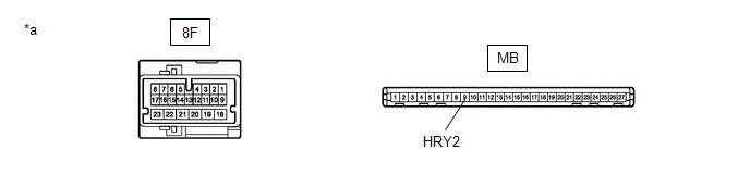
|
*a |
Component without harness connected (Power Distribution Box Assembly) |
- |
- |
(a) Remove the main body ECU (multiplex network body ECU) from the power distribution box assembly.
Click here
(b) Measure the resistance according to the value(s) in the table below.
Standard Resistance:
|
Tester Connection |
Condition |
Specified Condition |
|---|---|---|
|
8F-4 - MB-9 (HRY2) |
Always |
Below 1 Ω |
| OK |
|
| NG |
|
|
27. |
INSPECT NO. 1 INTEGRATION RELAY |
(a) Remove the No. 1 integration relay.
Click here
(b) Inspect the No. 1 integration relay.
Click here
| NG |
|
|
|
28. |
CHECK HARNESS AND CONNECTOR (NO. 1 INTEGRATION RELAY - HEADLIGHT UNIT ASSEMBLY RH) |
(a) Measure the resistance according to the value(s) in the table below.
Standard Resistance:
|
Tester Connection |
Condition |
Specified Condition |
|---|---|---|
|
9A-12 - A171-2 (LO) |
Always |
Below 1 Ω |
|
9A-12 or A171-2 (LO) - Body ground |
Always |
10 kΩ or higher |
| NG |
|
REPAIR OR REPLACE HARNESS OR CONNECTOR |
|
|
29. |
CHECK HARNESS AND CONNECTOR (POWER SOURCE - NO. 1 INTEGRATION RELAY) |
(a) Measure the voltage according to the value(s) in the table below.
Standard Voltage:
|
Tester Connection |
Condition |
Specified Condition |
|---|---|---|
|
9B-8 - Body ground |
Always*1 Ignition switch off*2 |
11 to 14 V |
- *1: for Gasoline Model
- *2: for HV Model
| NG |
|
REPAIR OR REPLACE HARNESS OR CONNECTOR |
|
|
30. |
CHECK HARNESS AND CONNECTOR (NO. 1 INTEGRATION RELAY - POWER DISTRIBUTION BOX ASSEMBLY) |
(a) Disconnect the 8F power distribution box assembly connector.
(b) Measure the resistance according to the value(s) in the table below.
Standard Resistance:
|
Tester Connection |
Condition |
Specified Condition |
|---|---|---|
|
9A-11 - 8F-4 |
Always |
Below 1 Ω |
|
9A-11 or 8F-4 - Body ground |
Always |
10 kΩ or higher |
| NG |
|
REPAIR OR REPLACE HARNESS OR CONNECTOR |
|
|
31. |
INSPECT POWER DISTRIBUTION BOX ASSEMBLY |

|
*a |
Component without harness connected (Power Distribution Box Assembly) |
- |
- |
(a) Remove the main body ECU (multiplex network body ECU) from the power distribution box assembly.
Click here
(b) Measure the resistance according to the value(s) in the table below.
Standard Resistance:
|
Tester Connection |
Condition |
Specified Condition |
|---|---|---|
|
8F-4 - MB-9 (HRY2) |
Always |
Below 1 Ω |
| OK |
|
| NG |
|
|
|
|