| Last Modified: 05-13-2024 | 6.11:8.1.0 | Doc ID: RM1000000026ZD4 |
| Model Year Start: 2023 | Model: Corolla | Prod Date Range: [09/2022 - ] |
| Title: 2ZR-FXE (ENGINE CONTROL): SFI SYSTEM: Fuel Injector Circuit; 2023 - 2025 MY Corolla Corolla HV [09/2022 - ] | ||
|
Fuel Injector Circuit |
DESCRIPTION
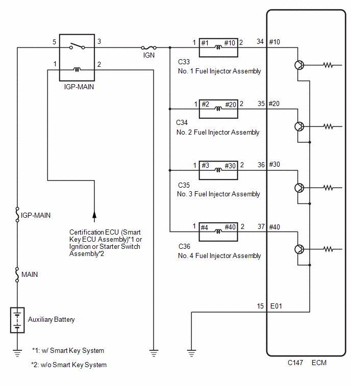
The fuel injector assemblies are located in each intake port and inject fuel into the cylinders based on the signals from the ECM.
WIRING DIAGRAM
CAUTION / NOTICE / HINT
NOTICE:
Inspect the fuses for circuits related to this system before performing the following procedure.
PROCEDURE
|
1. |
CHECK TERMINAL VOLTAGE (POWER SOURCE OF FUEL INJECTOR ASSEMBLY) |
|
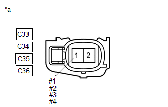
*a |
Front view of wire harness connector (to Fuel Injector Assembly) |
(a) Disconnect the fuel injector assembly connector.
(b) Turn the power switch on (IG).
(c) Measure the voltage according to the value(s) in the table below.
Standard Voltage:
|
Tester Connection |
Condition |
Specified Condition |
|---|---|---|
|
C33-1 (#1) - Body ground |
Power switch on (IG) |
11 to 14 V |
|
C34-1 (#2) - Body ground |
Power switch on (IG) |
11 to 14 V |
|
C35-1 (#3) - Body ground |
Power switch on (IG) |
11 to 14 V |
|
C36-1 (#4) - Body ground |
Power switch on (IG) |
11 to 14 V |
| NG |

|
|

|
2. |
INSPECT FUEL INJECTOR ASSEMBLY (INJECTION AND VOLUME) |
(a) Inspect the fuel injector assembly.
Click here
![2020 - 2025 MY Corolla Corolla HV [01/2019 - ]; 2ZR-FXE (FUEL): FUEL INJECTOR: INSPECTION](/t3Portal/stylegraphics/info.gif)
HINT:
Perform "Inspection After Repair" after replacing the fuel injector assembly.
Click here
| NG |
|
REPLACE FUEL INJECTOR ASSEMBLY
|
|
|
3. |
CHECK HARNESS AND CONNECTOR (FUEL INJECTOR ASSEMBLY - ECM) |
(a) Disconnect the fuel injector assembly connector.
(b) Disconnect the ECM connector.
(c) Measure the resistance according to the value(s) in the table below.
Standard Resistance:
|
Tester Connection |
Condition |
Specified Condition |
|---|---|---|
|
C33-2 (#10) - C147-34 (#10) |
Always |
Below 1 Ω |
|
C34-2 (#20) - C147-35 (#20) |
Always |
Below 1 Ω |
|
C35-2 (#30) - C147-36 (#30) |
Always |
Below 1 Ω |
|
C36-2 (#40) - C147-37 (#40) |
Always |
Below 1 Ω |
|
C33-2 (#10) or C147-34 (#10) - Body ground and other terminals |
Always |
10 kΩ or higher |
|
C34-2 (#20) or C147-35 (#20) - Body ground and other terminals |
Always |
10 kΩ or higher |
|
C35-2 (#30) or C147-36 (#30) - Body ground and other terminals |
Always |
10 kΩ or higher |
|
C36-2 (#40) or C147-37 (#40) - Body ground and other terminals |
Always |
10 kΩ or higher |
| OK |
|
PROCEED TO NEXT SUSPECTED AREA SHOWN IN PROBLEM SYMPTOMS TABLE |
| NG |
|
REPAIR OR REPLACE HARNESS OR CONNECTOR |
|
4. |
CHECK HARNESS AND CONNECTOR (IGP-MAIN RELAY - FUEL INJECTOR ASSEMBLY) |
(a) Disconnect the IGP-MAIN relay from No. 1 engine room relay block and No. 1 junction block assembly.
(b) Disconnect the fuel injector assembly connector.
(c) Measure the resistance according to the value(s) in the table below.
Standard Resistance:
|
Tester Connection |
Condition |
Specified Condition |
|---|---|---|
|
3 (IGP-MAIN relay) - C33-1 (#1) |
Always |
Below 1 Ω |
|
3 (IGP-MAIN relay) - C34-1 (#2) |
Always |
Below 1 Ω |
|
3 (IGP-MAIN relay) - C35-1 (#3) |
Always |
Below 1 Ω |
|
3 (IGP-MAIN relay) - C36-1 (#4) |
Always |
Below 1 Ω |
|
3 (IGP-MAIN relay) or C33-1 (#1) - Body ground and other terminals |
Always |
10 kΩ or higher |
|
3 (IGP-MAIN relay) or C34-1 (#2) - Body ground and other terminals |
Always |
10 kΩ or higher |
|
3 (IGP-MAIN relay) or C35-1 (#3) - Body ground and other terminals |
Always |
10 kΩ or higher |
|
3 (IGP-MAIN relay) or C36-1 (#4) - Body ground and other terminals |
Always |
10 kΩ or higher |
HINT:
If a short is detected in any of the above circuits, there may be a malfunction in the circuit of a connected ECU.
| OK |
|
| NG |
|
REPAIR OR REPLACE HARNESS OR CONNECTOR |
|
|
|