| Last Modified: 05-13-2024 | 6.11:8.1.0 | Doc ID: RM1000000026ZD1 |
| Model Year Start: 2023 | Model: Corolla | Prod Date Range: [09/2022 - ] |
| Title: 2ZR-FXE (ENGINE CONTROL): SFI SYSTEM: Fuel Pump Control Circuit; 2023 - 2025 MY Corolla Corolla HV [09/2022 - ] | ||
|
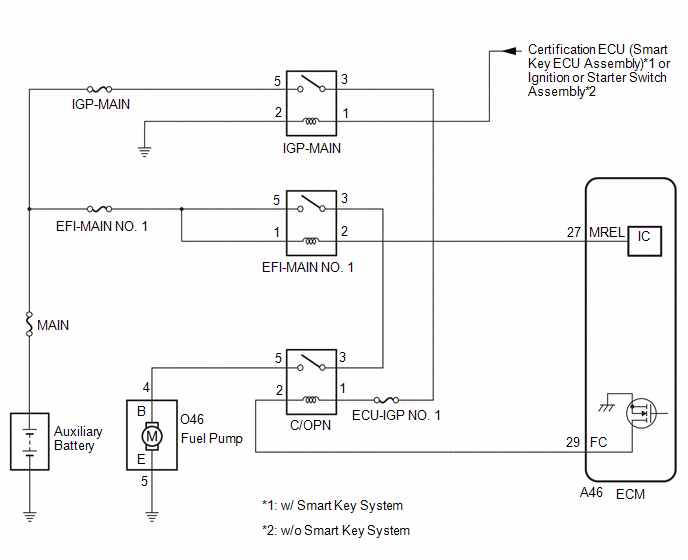
Fuel Pump Control Circuit |
DESCRIPTION
When the engine is being cranked, the start request signal output from the hybrid vehicle control ECU is input to the ECM, and the NE signal generated by the crankshaft position sensor is also input to the ECM. Thus, the ECM interprets that the engine is being cranked, and turns an internal transistor on, causing current to flow to the C/OPN relay. The fuel pump then operates the NE signal is input into the ECM with the engine running, the ECM keeps the transistor on.
WIRING DIAGRAM
CAUTION / NOTICE / HINT
NOTICE:
Inspect the fuses for circuits related to this system before performing the following procedure.
PROCEDURE
|
1. |
PERFORM ACTIVE TEST USING TECHSTREAM (ACTIVATE THE CIRCUIT RELAY) |
(a) Connect the Techstream to the DLC3.
(b) Turn the power switch on (IG).
(c) Turn the Techstream on.
(d) Enter the following menus: Powertrain / Engine / Active Test / Activate the Circuit Relay.
Powertrain > Engine > Active Test
|
Tester Display |
|---|
|
Activate the Circuit Relay |
(e) According to the display on the Techstream, perform the Active Test and check that fuel pump operating sounds can be heard.
OK:
Operating sounds can be heard from the fuel pump.
| NG |

|
|

|
2. |
READ VALUE USING TECHSTREAM (ENGINE SPEED) |
(a) Connect the Techstream to the DLC3.
(b) Turn the power switch on (IG).
(c) Turn the Techstream on.
(d) Put the engine in Inspection Mode (Maintenance Mode).
Click here
![2019 - 2025 MY Corolla Corolla Hatchback Corolla HV GR Corolla [06/2018 - ]; INTRODUCTION: REPAIR INSTRUCTION: INSPECTION MODE PROCEDURE](/t3Portal/stylegraphics/info.gif)
Powertrain > Hybrid Control > Utility
|
Tester Display |
|---|
|
Inspection Mode |
(e) Enter the following menus: Powertrain / Engine / Data List / Engine Speed.
Powertrain > Engine > Data List
|
Tester Display |
|---|
|
Engine Speed |
(f) Read the values displayed on the Techstream while the engine is cranking.
OK:
Values are displayed continuously.
| OK |
|
PROCEED TO NEXT SUSPECTED AREA SHOWN IN PROBLEM SYMPTOMS TABLE |
| NG |
|
|
3. |
INSPECT RELAY (C/OPN RELAY) |
(a) Inspect the C/OPN relay.
Click here
| NG |
|
REPLACE RELAY (C/OPN RELAY) |
|
|
4. |
CHECK TERMINAL VOLTAGE (POWER SOURCE OF C/OPN RELAY) |
(a) Remove the C/OPN relay from the No. 2 relay block assembly.
(b) Turn the power switch on (IG).
(c) Measure the voltage according to the value(s) in the table below.
Standard Voltage:
|
Tester Connection |
Condition |
Specified Condition |
|---|---|---|
|
1 (C/OPN relay) - Body ground |
Power switch on (IG) |
11 to 14 V |
|
3 (C/OPN relay) - Body ground |
Power switch on (IG) |
11 to 14 V |
| NG |
|
|
|
5. |
CHECK HARNESS AND CONNECTOR (C/OPN RELAY - ECM) |
(a) Remove the C/OPN relay from the No. 2 relay block assembly.
(b) Disconnect the ECM connector.
(c) Measure the resistance according to the value(s) in the table below.
Standard Resistance:
|
Tester Connection |
Condition |
Specified Condition |
|---|---|---|
|
2 (C/OPN relay) - A46-29 (FC) |
Always |
Below 1 Ω |
|
2 (C/OPN relay) or A46-29 (FC) - Body ground and other terminals |
Always |
10 kΩ or higher |
| NG |
|
REPAIR OR REPLACE HARNESS OR CONNECTOR |
|
|
6. |
CHECK HARNESS AND CONNECTOR (C/OPN RELAY - FUEL PUMP) |
(a) Remove the C/OPN relay from the No. 2 relay block assembly.
(b) Disconnect the fuel pump connector.
(c) Measure the resistance according to the value(s) in the table below.
Standard Resistance:
|
Tester Connection |
Condition |
Specified Condition |
|---|---|---|
|
5 (C/OPN relay) - O46-4 (B) |
Always |
Below 1 Ω |
|
5 (C/OPN relay) or O46-4 (B) - Body ground and other terminals |
Always |
10 kΩ or higher |
| NG |
|
REPAIR OR REPLACE HARNESS OR CONNECTOR |
|
|
7. |
CHECK HARNESS AND CONNECTOR (FUEL PUMP - BODY GROUND) |
(a) Disconnect the fuel pump connector.
(b) Measure the resistance according to the value(s) in the table below.
Standard Resistance:
|
Tester Connection |
Condition |
Specified Condition |
|---|---|---|
|
O46-5 (E) - Body ground |
Always |
Below 1 Ω |
| NG |
|
REPAIR OR REPLACE HARNESS OR CONNECTOR |
|
|
8. |
INSPECT FUEL PUMP |
(a) Inspect the fuel pump.
w/ Canister Pump Module:
w/o Canister Pump Module:
HINT:
Perform "Inspection After Repair" after replacing the fuel pump.
Click here
| OK |
|
REPLACE ECM
|
| NG |
|
REPLACE FUEL PUMP w/ Canister Pump Module:
w/o Canister Pump Module:
|
|
9. |
CHECK HARNESS AND CONNECTOR (IGP-MAIN RELAY - C/OPN RELAY) |
(a) Remove the IGP-MAIN relay from the No. 1 junction block and No. 1 relay block assembly.
(b) Remove the C/OPN relay from the No. 2 relay block assembly.
(c) Measure the resistance according to the value(s) in the table below.
Standard Resistance:
|
Tester Connection |
Condition |
Specified Condition |
|---|---|---|
|
3 (IGP-MAIN) - 1 (C/OPN relay) |
Always |
Below 1 Ω |
|
3 (IGP-MAIN) or 1 (C/OPN relay) - Body ground and other terminals |
Always |
10 kΩ or higher |
HINT:
If a short is detected in any of the above circuits, there may be a malfunction in the circuit of a connected ECU.
| NG |
|
REPAIR OR REPLACE HARNESS OR CONNECTOR |
|
|
10. |
CHECK HARNESS AND CONNECTOR (EFI-MAIN NO. 1 RELAY - C/OPN RELAY) |
(a) Remove the EFI-MAIN NO. 1 relay from the No. 1 junction block and No. 1 relay block assembly.
(b) Remove the C/OPN relay from the No. 2 relay block assembly.
(c) Measure the resistance according to the value(s) in the table below.
Standard Resistance:
|
Tester Connection |
Condition |
Specified Condition |
|---|---|---|
|
3 (EFI-MAIN NO. 1) - 3 (C/OPN relay) |
Always |
Below 1 Ω |
|
3 (EFI-MAIN NO. 1) or 3 (C/OPN relay) - Body ground and other terminals |
Always |
10 kΩ or higher |
HINT:
If a short is detected in any of the above circuits, there may be a malfunction in the circuit of a connected ECU.
| OK |
|
| NG |
|
REPAIR OR REPLACE HARNESS OR CONNECTOR |
|
|
|