| Last Modified: 05-13-2024 | 6.11:8.1.0 | Doc ID: RM1000000026ZA1 |
| Model Year Start: 2023 | Model: GR Corolla | Prod Date Range: [09/2022 - 11/2022] |
| Title: HEATING / AIR CONDITIONING: AIR CONDITIONING SYSTEM (for TMC Made, and Gasoline Model, with Manual Air Conditioning System for Electrical Control Type): P053015; Refrigerant Pressure Sensor Circuit Short to Battery or Open; 2023 MY Corolla Corolla Hatchback GR Corolla [09/2022 - 11/2022] | ||
|
DTC |
P053015 |
Refrigerant Pressure Sensor Circuit Short to Battery or Open |
DESCRIPTION
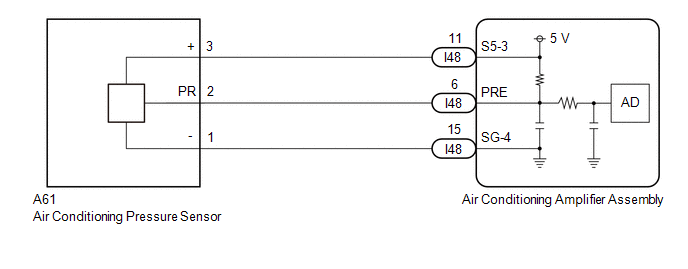
The air conditioning pressure sensor, which is installed to the high pressure side pipe to detect refrigerant pressure, sends a refrigerant pressure signal to the air conditioning amplifier assembly. The air conditioning amplifier assembly converts this signal to a pressure value according to the sensor characteristics and uses it to control the compressor.
|
DTC No. |
Detection Item |
DTC Detection Condition |
Trouble Area |
Memory |
|---|---|---|---|---|
|
P053015 |
Refrigerant Pressure Sensor Circuit Short to Battery or Open |
Diagnosis Condition:
Malfunction:
Detection Time:
|
|
Memorized |
DTC Detection Condition Combination Table
|
Vehicle Condition |
|||
|---|---|---|---|
|
Pattern 1 |
Pattern 2 |
||
|
Diagnosis Condition |
Ignition switch ON |
○ |
○ |
|
Malfunction |
Open in air conditioning pressure sensor circuit |
○ |
- |
|
Short (+B) in air conditioning pressure sensor circuit |
- |
○ |
|
|
Detection Time |
Continuously for 4 seconds or more |
Continuously for 4 seconds or more |
|
|
Trip Count |
1 trip |
1 trip |
|
HINT:
If the conditions of either of these patterns are detected, a DTC will be stored.
WIRING DIAGRAM
CAUTION / NOTICE / HINT
NOTICE:
If DTC P05347A is output at the same time, perform troubleshooting for DTC P05347A first.
Click here
![2023 MY Corolla Corolla Hatchback GR Corolla [09/2022 - 11/2022]; HEATING / AIR CONDITIONING: AIR CONDITIONING SYSTEM (for TMC Made, and Gasoline Model, with Manual Air Conditioning System for Electrical Control Type): P05347A; Refrigerant Gas Fluid Leak or Seal Failure](/t3Portal/stylegraphics/info.gif)
HINT:
If a connector is disconnected or not installed correctly, securely connect it and check for DTCs.
PROCEDURE
|
1. |
CHECK COMPARE REFRIGERANT GAS PRESSURE VALUES SHOWN ON GTS AND MANIFOLD GAUGE SET |
(a) Install a manifold gauge set.
Click here
(b) Compare the values displayed in the Data List and on the manifold gauge.
Body Electrical > Air Conditioner > Data List
|
Tester Display |
Measurement Item |
Range |
Normal Condition |
Diagnostic Note |
|---|---|---|---|---|
|
Regulator Pressure Sensor |
Air conditioning pressure sensor |
-32768 to 32767 kPa(gauge) |
Actual refrigerant pressure displayed |
|
Body Electrical > Air Conditioner > Data List
|
Tester Display |
|---|
|
Regulator Pressure Sensor |
|
Result |
Proceed to |
|---|---|
|
Data List value and manifold gauge set value do not match |
A |
|
Data List value matches manifold gauge set value |
B |
| B |

|
|

|
2. |
CHECK HARNESS AND CONNECTOR (AIR CONDITIONING PRESSURE SENSOR - BODY GROUND) |
|
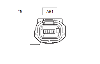
(a) Disconnect the A61 air conditioning pressure sensor connector. |
|
(b) Measure the resistance according to the value(s) in the table below.
Standard Resistance:
|
Tester Connection |
Condition |
Specified Condition |
|---|---|---|
|
A61-1 (-) - Body ground |
Always |
Below 1 Ω |
| NG |
|
|
|
3. |
CHECK HARNESS AND CONNECTOR (AIR CONDITIONING PRESSURE SENSOR - BODY GROUND) |
(a) Disconnect the A61 air conditioning pressure sensor connector.
|
(b) Measure the voltage according to the value(s) in the table below. Standard Voltage:
|
|
|
Result |
Proceed to |
|---|---|
|
5.25 V or higher |
A |
|
3.0 to 5.25 V |
B |
|
Below 3.0 V |
C |
| B |
|
| C |
|
|
|
4. |
CHECK HARNESS AND CONNECTOR (AIR CONDITIONING AMPLIFIER ASSEMBLY - AIR CONDITIONING PRESSURE SENSOR) |
(a) Disconnect the A61 air conditioning pressure sensor connector.
(b) Disconnect the I48 air conditioning amplifier assembly connector.
(c) Measure the resistance according to the value(s) in the table below.
Standard Resistance:
|
Tester Connection |
Condition |
Specified Condition |
|---|---|---|
|
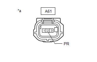
A61-2 (PR) or I48-6 (PRE) - Other terminals and body ground |
Always |
10 kΩ or higher |
| OK |
|
| NG |
|
REPAIR OR REPLACE HARNESS OR CONNECTOR |
|
5. |
CHECK AIR CONDITIONING AMPLIFIER ASSEMBLY (INTERNAL CIRCUIT RESISTANCE) |
(a) Disconnect the A61 air conditioning pressure sensor connector.
|
(b) Measure the resistance according to the value(s) in the table below. Standard Resistance:
HINT: After turning the ignition switch off, wait at least 30 seconds before performing the measurement. |
|
| OK |
|
|
|
6. |
CHECK HARNESS AND CONNECTOR (AIR CONDITIONING PRESSURE SENSOR - AIR CONDITIONING AMPLIFIER ASSEMBLY) |
(a) Disconnect the A61 air conditioning pressure sensor connector.
(b) Disconnect the I48 air conditioning amplifier assembly connector.
(c) Measure the resistance according to the value(s) in the table below.
Standard Resistance:
|
Tester Connection |
Condition |
Specified Condition |
|---|---|---|
|
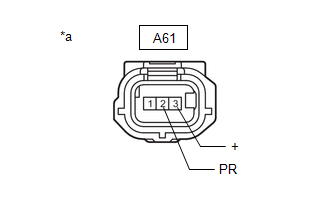
A61-2 (PR) - A61-3 (+) |
Always |
10 kΩ or higher |
|
I48-6 (PRE) - I48-11 (S5-3) |
Always |
10 kΩ or higher |
| OK |
|
| NG |
|
REPAIR OR REPLACE HARNESS OR CONNECTOR |
|
7. |
CHECK HARNESS AND CONNECTOR (AIR CONDITIONING AMPLIFIER ASSEMBLY - AIR CONDITIONING PRESSURE SENSOR) |
(a) Disconnect the A61 air conditioning pressure sensor connector.
(b) Disconnect the I48 air conditioning amplifier assembly connector.
(c) Measure the resistance according to the value(s) in the table below.
Standard Resistance:
|
Tester Connection |
Condition |
Specified Condition |
|---|---|---|
|
A61-2 (PR) - I48-6 (PRE) |
Always |
Below 1 Ω |
| OK |
|
| NG |
|
REPAIR OR REPLACE HARNESS OR CONNECTOR |
|
8. |
CHECK HARNESS AND CONNECTOR (AIR CONDITIONING AMPLIFIER ASSEMBLY - AIR CONDITIONING PRESSURE SENSOR) |
(a) Disconnect the A61 air conditioning pressure sensor connector.
(b) Disconnect the I48 air conditioning amplifier assembly connector.
(c) Measure the resistance according to the value(s) in the table below.
Standard Resistance:
|
Tester Connection |
Condition |
Specified Condition |
|---|---|---|
|
A61-1 (-) - I48-15 (SG-4) |
Always |
Below 1 Ω |
| OK |
|
| NG |
|
REPAIR OR REPLACE HARNESS OR CONNECTOR |
|
|
|