| Last Modified: 05-13-2024 | 6.11:8.1.0 | Doc ID: RM1000000026Z8I |
| Model Year Start: 2023 | Model: GR Corolla | Prod Date Range: [09/2022 - 11/2022] |
| Title: HEATING / AIR CONDITIONING: AIR CONDITIONING SYSTEM (for TMC Made, and Gasoline Model, with Automatic Air Conditioning System): P007015; Ambient Temperature Sensor Circuit Short to Battery or Open; 2023 MY Corolla Corolla Hatchback GR Corolla [09/2022 - 11/2022] | ||
|
DTC |
P007015 |
Ambient Temperature Sensor Circuit Short to Battery or Open |
DESCRIPTION
The ambient temp. sensor (thermistor assembly) is installed in front of the cooler condenser assembly to detect the ambient temperature, which is used to control the air conditioning system. This sensor is connected to the air conditioning amplifier assembly and detects fluctuations in the ambient temperature. This data is used for controlling the cabin temperature. The sensor sends a signal to the air conditioning amplifier assembly. The resistance of the ambient temp. sensor (thermistor assembly) changes in accordance with the ambient temperature. As the temperature decreases, the resistance increases. As the temperature increases, the resistance decreases.
The air conditioning amplifier assembly applies voltage (5 V) to the ambient temp. sensor (thermistor assembly) and reads voltage changes due to changes in the resistance of the ambient temp. sensor (thermistor assembly).
|
DTC No. |
Detection Item |
DTC Detection Condition |
Trouble Area |
Memory |
|---|---|---|---|---|
|
P007015 |
Ambient Temperature Sensor Circuit Short to Battery or Open |
Diagnosis Condition:
Malfunction:
Detection Time:
|
|
Memorized |
DTC Detection Condition Combination Table
|
Vehicle Condition |
|||
|---|---|---|---|
|
Pattern 1 |
Pattern 2 |
||
|
Diagnosis Condition |
Ignition switch ON |
○ |
○ |
|
Malfunction |
Open in ambient temperature sensor circuit |
○ |
- |
|
Short (+B) in ambient temperature sensor circuit |
- |
○ |
|
|
Detection Time |
Continuously for 4 seconds or more |
Continuously for 4 seconds or more |
|
|
Trip Count |
1 trip |
1 trip |
|
HINT:
If the conditions of either of these patterns are detected, a DTC will be stored.
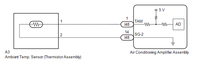
WIRING DIAGRAM
PROCEDURE
|
1. |
READ VALUE USING GTS (AMBIENT TEMPERATURE SENSOR) |
(a) Read the Data List according to the display on the GTS.
Body Electrical > Air Conditioner > Data List
|
Tester Display |
Measurement Item |
Range |
Normal Condition |
Diagnostic Note |
|---|---|---|---|---|
|
Ambient Temperature Sensor |
Ambient temp. sensor (thermistor assembly) |
-327.68 to 327.67°C |
Actual ambient temperature displayed |
Ambient temp. sensor (thermistor assembly) circuit malfunction |
Body Electrical > Air Conditioner > Data List
|
Tester Display |
|---|
|
Ambient Temperature Sensor |
OK:
The display is as specified in the normal condition column.
| OK |

|
|

|
2. |
INSPECT AMBIENT TEMP. SENSOR (THERMISTOR ASSEMBLY) |
except G16E-GTS: Click here
![2019 - 2025 MY Corolla Corolla Hatchback Corolla HV [06/2018 - ]; HEATING / AIR CONDITIONING: AMBIENT TEMPERATURE SENSOR (except G16E-GTS): INSPECTION](/t3Portal/stylegraphics/info.gif)
for G16E-GTS: Click here
| NG |
|
REPLACE AMBIENT TEMP. SENSOR (THERMISTOR ASSEMBLY) except G16E-GTS: Click here
for G16E-GTS: Click here
|
|
|
3. |
CHECK HARNESS AND CONNECTOR (AIR CONDITIONING AMPLIFIER ASSEMBLY - AMBIENT TEMP. SENSOR (THERMISTOR ASSEMBLY)) |
(a) Disconnect the A3 ambient temp. sensor (thermistor assembly) connector.
(b) Disconnect the I48 air conditioning amplifier assembly connector.
(c) Measure the resistance according to the value(s) in the table below.
Standard Resistance:
|
Tester Connection |
Condition |
Specified Condition |
|---|---|---|
|
A3-1 - I48-1 (TAM) |
Always |
Below 1 Ω |
|
A3-2 - I48-14 (SG-2) |
Always |
Below 1 Ω |
(d) Measure the voltage according to the value(s) in the table below.
Standard Voltage:
|
Tester Connection |
Condition |
Specified Condition |
|---|---|---|
|
I48-1 (TAM) - Body ground |
Ignition switch ON |
Below 1 V |
|
I48-14 (SG-2) - Body ground |
Ignition switch ON |
Below 1 V |
| OK |
|
| NG |
|
REPAIR OR REPLACE HARNESS OR CONNECTOR |
|
|
|