| Last Modified: 05-13-2024 | 6.11:8.1.0 | Doc ID: RM1000000026Z8D |
| Model Year Start: 2023 | Model: GR Corolla | Prod Date Range: [09/2022 - 11/2022] |
| Title: HEATING / AIR CONDITIONING: AIR CONDITIONING SYSTEM (for TMC Made, and Gasoline Model, with Automatic Air Conditioning System): B142A88; Servo Motor LIN Communication Bus off; 2023 MY Corolla Corolla Hatchback GR Corolla [09/2022 - 11/2022] | ||
|
DTC |
B142A88 |
Servo Motor LIN Communication Bus off |
DESCRIPTION
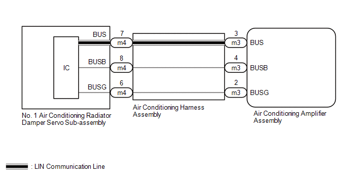
The air conditioning harness assembly connects the air conditioning amplifier assembly and the servo motors.
The air conditioning amplifier assembly supplies power and sends operation instructions to each servo motor through the air conditioning harness assembly.
Each servo motor sends damper position information to the air conditioning amplifier assembly.
|
DTC No. |
Detection Item |
DTC Detection Condition |
Trouble Area |
Memory |
|---|---|---|---|---|
|
B142A88 |
Servo Motor LIN Communication Bus off |
Diagnosis Condition:
Malfunction:
Detection Time:
|
|
Memorized |
DTC Detection Condition Combination Table
|
Vehicle Condition |
|||
|---|---|---|---|
|
Pattern 1 |
Pattern 2 |
||
|
Diagnosis Condition |
Ignition switch ON |
○ |
○ |
|
Malfunction |
Error in communication line between air conditioning amplifier assembly and each servo motor |
○ |
- |
|
Open in communication line between air conditioning amplifier assembly and each servo motor |
- |
○ |
|
|
Detection Time |
Continuously for 10 seconds or more |
Continuously for 10 seconds or more |
|
|
Trip Count |
1 trip |
1 trip |
|
HINT:
If the conditions of either of these patterns are detected, a DTC will be stored.
WIRING DIAGRAM
PROCEDURE
|
1. |
CHECK AIR CONDITIONING AMPLIFIER ASSEMBLY |
NOTICE:
When inspecting the air conditioning amplifier assembly, be careful not to cause a short.
(a) Disconnect the m3 air conditioning amplifier assembly connector.
|
*a |
Component without harness connected (Air Conditioning Amplifier Assembly) |
- |
- |
(b) Measure the resistance according to the value(s) in the table below.
Standard Resistance:
|
Tester Connection |
Condition |
Specified Condition |
|---|---|---|
|
m3-2 (BUSG) - Body ground |
Always |
Below 1 Ω |
(c) Measure the voltage according to the value(s) in the table below.
Standard Voltage:
|
Tester Connection |
Condition |
Specified Condition |
|---|---|---|
|
m3-4 (BUSB) - m3-2 (BUSG) |
Ignition switch off |
11 to 14 V |
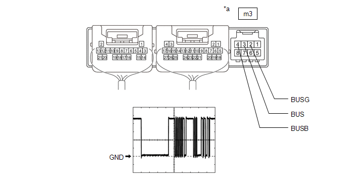
(d) Using an oscilloscope, check the waveform.
|
Item |
Content |
|---|---|
|
Tester Connection |
m3-3 (BUS) - m3-2 (BUSG) |
|
Tool Setting |
2 V/DIV., 20 μs/DIV. |
|
Condition |
Ignition switch ON |
OK:
The waveform displays properly.
| NG |

|
|

|
2. |
CHECK AIR CONDITIONING HARNESS ASSEMBLY |
(a) Disconnect the m3 air conditioning amplifier assembly connector.
(b) Disconnect the m4 No. 1 air conditioning radiator damper servo sub-assembly connector.
(c) Measure the resistance according to the value(s) in the table below.
Standard Resistance:
|
Tester Connection |
Condition |
Specified Condition |
|---|---|---|
|
m3-2 (BUSG) - m4-6 (BUSG) |
Always |
Below 1 Ω |
|
m3-3 (BUS) - m4-7 (BUS) |
Always |
Below 1 Ω |
|
m3-4 (BUSB) - m4-8 (BUSB) |
Always |
Below 1 Ω |
| OK |
|
REPLACE NO. 1 AIR CONDITIONING RADIATOR DAMPER SERVO SUB-ASSEMBLY |
| NG |
|
|
|
|