| Last Modified: 07-31-2024 | 6.11:8.1.0 | Doc ID: RM1000000026Z3U |
| Model Year Start: 2023 | Model: Corolla | Prod Date Range: [09/2022 - ] |
| Title: HEATING / AIR CONDITIONING: AIR CONDITIONING SYSTEM (for HV Model): B141A15; Room Temperature Sensor Circuit Short to Battery or Open; 2023 - 2025 MY Corolla Corolla HV [09/2022 - ] | ||
|
DTC |
B141A15 |
Room Temperature Sensor Circuit Short to Battery or Open |
DESCRIPTION
The room temp. sensor (cooler thermistor) is installed in the instrument panel to detect the cabin temperature, which is used to control the air conditioning system. The resistance of the room temp. sensor (cooler thermistor) changes in accordance with the cabin temperature. As the temperature decreases, the resistance increases. As the temperature increases, the resistance decreases.
The air conditioning amplifier assembly applies voltage to the room temp. sensor (cooler thermistor) and reads voltage changes due to changes in the resistance of the room temp. sensor (cooler thermistor).
|
DTC No. |
Detection Item |
DTC Detection Condition |
Trouble Area |
Memory |
|---|---|---|---|---|
|
B141A15 |
Room Temperature Sensor Circuit Short to Battery or Open |
Diagnosis Condition:
Malfunction:
Detection Time:
|
|
Memorized |
DTC Detection Condition Combination Table
|
Vehicle Condition |
|||
|---|---|---|---|
|
Pattern 1 |
Pattern 2 |
||
|
Diagnosis Condition |
Ignition switch ON |
○ |
○ |
|
Malfunction |
Open in room temperature sensor circuit |
○ |
- |
|
Short (+B) in room temperature sensor circuit |
- |
○ |
|
|
Detection Time |
Continuously for 4 seconds or more |
Continuously for 4 seconds or more |
|
|
Trip Count |
1 trip |
1 trip |
|
HINT:
If the conditions of either of these patterns are detected, a DTC will be stored.
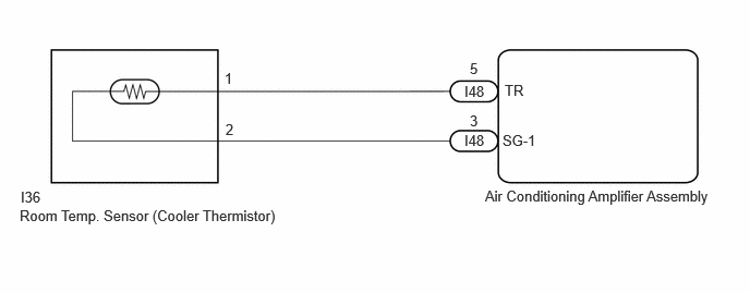
WIRING DIAGRAM

PROCEDURE
|
1. |
CHECK ROOM TEMP. SENSOR (COOLER THERMISTOR) CIRCUIT |
|
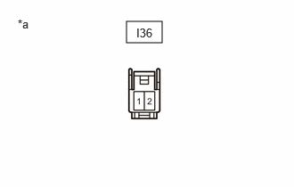
(a) Disconnect the I36 room temp. sensor (cooler thermistor) connector. |
|
(b) Measure the voltage according to the value(s) in the table below.
Standard Voltage:
|
Tester Connection |
Condition |
Specified Condition |
|---|---|---|
|
I36-1 - Body ground |
Ignition switch ON |
0 to 5.5 V |
| NG |

|
|
|
2. |
CLEAR DTC |
(a) Clear the DTCs.
Body Electrical > Air Conditioner > Clear DTCs
|
|
3. |
CHECK FOR DTC |
(a) Turn the ignition switch off.
|
(b) Disconnect the I36 room temp. sensor (cooler thermistor) connector. |
|
|
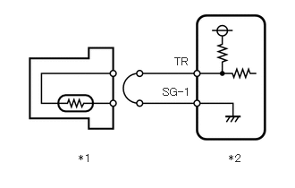
(c) Connect terminals 1 and 2 of the room temp. sensor (cooler thermistor) connector on the wire harness side. |
|
(d) Turn the ignition switch to ON and wait for 4 seconds or more.
(e) Check for DTCs.
Body Electrical > Air Conditioner > Trouble Codes
|
Result |
Proceed to |
|---|---|
|
B141A11 is output |
A |
|
B141A15 is output |
B |
| A |

|
|
|
4. |
CHECK HARNESS AND CONNECTOR (AIR CONDITIONING AMPLIFIER ASSEMBLY - ROOM TEMP. SENSOR (COOLER THERMISTOR)) |
(a) Disconnect the I36 room temp. sensor (cooler thermistor) connector.
(b) Disconnect the I48 air conditioning amplifier assembly connector.
(c) Measure the resistance according to the value(s) in the table below.
Standard Resistance:
|
Tester Connection |
Condition |
Specified Condition |
|---|---|---|
|
I36-1 - I48-5 (TR) |
Always |
Below 1 Ω |
|
I36-2 - I48-3 (SG-1) |
Always |
Below 1 Ω |
| OK |

|
| NG |

|
REPAIR OR REPLACE HARNESS OR CONNECTOR |
|
5. |
CHECK HARNESS AND CONNECTOR (AIR CONDITIONING AMPLIFIER ASSEMBLY - ROOM TEMP. SENSOR (COOLER THERMISTOR)) |
(a) Disconnect the I36 room temp. sensor (cooler thermistor) connector.
(b) Disconnect the I48 air conditioning amplifier assembly connector.
(c) Measure the resistance according to the value(s) in the table below.
Standard Resistance:
|
Tester Connection |
Condition |
Specified Condition |
|---|---|---|
|
I36-1 or I48-5 (TR) - Other terminals and body ground |
Always |
10 kΩ or higher |
| OK |

|
| NG |

|
REPAIR OR REPLACE HARNESS OR CONNECTOR |
|
|
|


![2023 MY Corolla Corolla Hatchback Corolla HV GR Corolla [09/2022 - 11/2022]; HEATING / AIR CONDITIONING: AIR CONDITIONING AMPLIFIER: REMOVAL](/t3Portal/stylegraphics/info.gif)