| Last Modified: 01-27-2025 | 6.11:8.1.0 | Doc ID: RM1000000026Z3N |
| Model Year Start: 2023 | Model: GR Corolla | Prod Date Range: [09/2022 - ] |
| Title: AUDIO / VIDEO: AUDIO AND VISUAL SYSTEM (for 8 Inch Display Type (w/ Single Knob Type) or 10.5 Inch Display Type): Sound cannot be Heard Sound Quality is Poor only when Replaying USB Storage Device or "iPod"; 2023 - 2025 MY Corolla Corolla Hatchback Corolla HV GR Corolla [09/2022 - ] | ||
|
Sound cannot be Heard Sound Quality is Poor only when Replaying USB Storage Device or "iPod" |
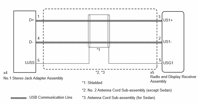
WIRING DIAGRAM
CAUTION / NOTICE / HINT
NOTICE:
Depending on the parts that are replaced during vehicle inspection or maintenance, performing initialization, registration or calibration may be needed.
Click here
![2023 - 2025 MY Corolla Corolla Hatchback Corolla HV GR Corolla [09/2022 - ]; AUDIO / VIDEO: AUDIO AND VISUAL SYSTEM (for Knobless Radio and Display Receiver): PRECAUTION](/t3Portal/stylegraphics/info.gif)
PROCEDURE
|
1. |
CHECK MODEL |
(a) Choose the model to be inspected.
|
Result |
Proceed to |
|---|---|
|
for Sedan, LHD |
A |
|
except Sedan, LHD |
B |
| B |

|
|

|
2. |
INSPECT ANTENNA CORD SUB-ASSEMBLY (RADIO AND DISPLAY RECEIVER ASSEMBLY - NO. 1 STEREO JACK ADAPTER ASSEMBLY) |
(a) Disconnect the x5 radio and display receiver assembly connector.
(b) Disconnect the x4 No. 1 stereo jack adapter assembly connector.
(c) Measure the resistance according to the value(s) in the table below.
Standard Resistance:
|
Tester Connection |
Condition |
Specified Condition |
|---|---|---|
|
x5-2 (US1-) - x4-4 (D-) |
Always |
Below 1 Ω |
|
x5-3 (US1+) - x4-1 (D+) |
Always |
Below 1 Ω |
|
x5-5 (USG1) - x4-5 (UJSS) |
Always |
Below 1 Ω |
|
x5-2 (US1-) or x4-4 (D-) - Body ground |
Always |
10 kΩ or higher |
|
x5-3 (US1+) or x4-1 (D+) - Body ground |
Always |
10 kΩ or higher |
|
x5-5 (USG1) or x4-5 (UJSS) - Body ground |
Always |
10 kΩ or higher |
| NG |
|
REPLACE ANTENNA CORD SUB-ASSEMBLY
Click here
|
|
|
3. |
CHECK NO. 1 STEREO JACK ADAPTER ASSEMBLY |
(a) Replace the No. 1 stereo jack adapter assembly with a new or known good one.
Click here
(b) Check if the problem symptom recurs.
|
Result |
Proceed to |
|---|---|
|
Malfunction disappears |
A |
|
Malfunction occurs |
B |
| A |
|
END (NO. 1 STEREO JACK ADAPTER ASSEMBLY MALFUNCTION) |
| B |
|
REPLACE RADIO AND DISPLAY RECEIVER ASSEMBLY
Click here
|
|
4. |
INSPECT NO. 2 ANTENNA CORD SUB-ASSEMBLY (RADIO AND DISPLAY RECEIVER ASSEMBLY - NO. 1 STEREO JACK ADAPTER ASSEMBLY) |
(a) Disconnect the x5 radio and display receiver assembly connector.
(b) Disconnect the x4 No. 1 stereo jack adapter assembly connector.
(c) Measure the resistance according to the value(s) in the table below.
Standard Resistance:
|
Tester Connection |
Condition |
Specified Condition |
|---|---|---|
|
x5-2 (US1-) - x4-4 (D-) |
Always |
Below 1 Ω |
|
x5-3 (US1+) - x4-1 (D+) |
Always |
Below 1 Ω |
|
x5-5 (USG1) - x4-5 (UJSS) |
Always |
Below 1 Ω |
|
x5-2 (US1-) or x4-4 (D-) - Body ground |
Always |
10 kΩ or higher |
|
x5-3 (US1+) or x4-1 (D+) - Body ground |
Always |
10 kΩ or higher |
|
x5-5 (USG1) or x4-5 (UJSS) - Body ground |
Always |
10 kΩ or higher |
| NG |
|
REPLACE NO. 2 ANTENNA CORD SUB-ASSEMBLY
Click here
|
|
|
5. |
CHECK NO. 1 STEREO JACK ADAPTER ASSEMBLY |
(a) Replace the No. 1 stereo jack adapter assembly with a new or known good one.
Click here
(b) Check if the problem symptom recurs.
|
Result |
Proceed to |
|---|---|
|
Malfunction disappears |
A |
|
Malfunction occurs |
B |
| A |
|
END (NO. 1 STEREO JACK ADAPTER ASSEMBLY MALFUNCTION) |
| B |
|
REPLACE RADIO AND DISPLAY RECEIVER ASSEMBLY
Click here
|
|
|
|