| Last Modified: 01-27-2025 | 6.11:8.1.0 | Doc ID: RM1000000026XS4 |
| Model Year Start: 2023 | Model: GR Corolla | Prod Date Range: [09/2022 - ] |
| Title: EA67F / EA68F (MANUAL TRANSMISSION / TRANSAXLE): OUTPUT SHAFT: INSPECTION; 2023 - 2025 MY Corolla Corolla Hatchback GR Corolla [09/2022 - ] | ||
INSPECTION
PROCEDURE
1. INSPECT NO. 1 OUTPUT SHAFT
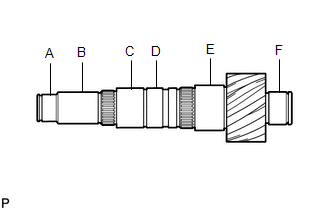
(a) Check the No. 1 output shaft for wear and damage.
|
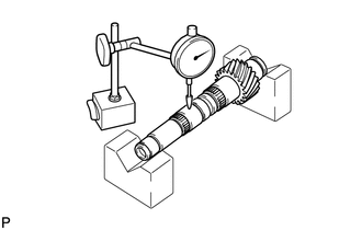
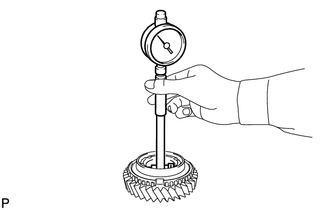
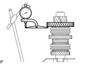
(b) Using a dial indicator, check the No. 1 output shaft runout. Maximum Runout: 0.01 mm (0.000394 in.) If the runout exceeds the maximum, replace the No. 1 output shaft. |
|
|
(c) Using a micrometer, measure the outer diameter of the No. 1 output shaft journal surface. Standard:
If the outer diameter is below the minimum, replace the No. 1 output shaft. |
|
2. INSPECT 1ST DRIVEN GEAR
|
(a) Using a cylinder gauge, measure the inside diameter of the 1st driven gear. Standard Inside Diameter: 53.015 to 53.040 mm (2.0872 to 2.0882 in.) Maximum Inside Diameter: 53.040 mm (2.0882 in.) If the inside diameter exceeds the maximum, replace the 1st driven gear. |
|
3. INSPECT 2ND DRIVEN GEAR
|
(a) Using a cylinder gauge, measure the inside diameter of the 2nd driven gear. Standard Inside Diameter: 56.015 to 56.030 mm (2.2053 to 2.2059 in.) Maximum Inside Diameter: 56.030 mm (2.2059 in.) If the inside diameter exceeds the maximum, replace the 2nd driven gear. |
|
4. INSPECT 3RD DRIVEN GEAR
|
(a) Using a cylinder gauge, measure the inside diameter of the 3rd driven gear. Standard Inside Diameter: 42.015 to 42.040 mm (1.6541 to 1.6551 in.) Maximum Inside Diameter: 42.040 mm (1.6551 in.) If the inside diameter exceeds the maximum, replace the 3rd driven gear. |
|
5. INSPECT 4TH DRIVEN GEAR
|
(a) Using a cylinder gauge, measure the inside diameter of the 4th driven gear. Standard Inside Diameter: 48.015 to 48.040 mm (1.8904 to 1.8913 in.) Maximum Inside Diameter: 48.040 mm (1.8913 in.) If the inside diameter exceeds the maximum, replace the 4th driven gear. |
|
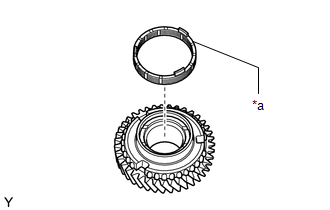
6. INSPECT 1ST DRIVEN GEAR SYNCHRONIZER RING SET
(a) Coat the 1st driven gear synchronizer ring set with gear oil.
|
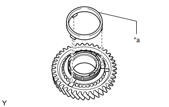
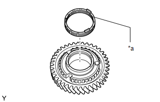
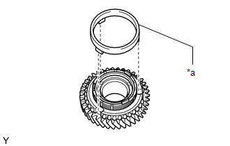
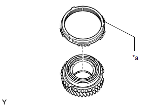
(b) Install the inner ring to the 1st driven gear. |
|
|
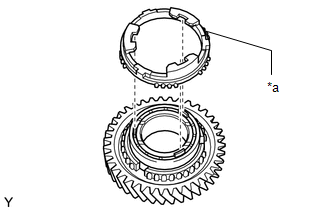
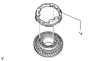
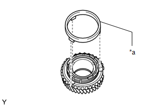
(c) Install the middle ring to the 1st driven gear. |
|
|
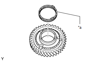
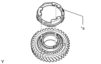
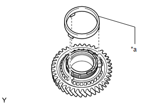
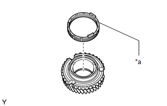
(d) Install the outer ring to the 1st driven gear. |
|
(e) Coat the 1st driven gear with gear oil.
|
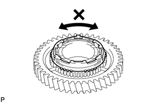
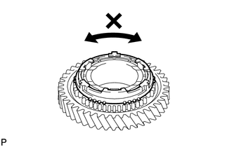
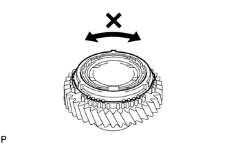
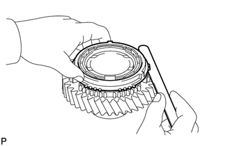
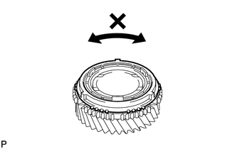
(f) Check that the 1st driven gear synchronizer ring set does not turn when the 1st driven gear synchronizer ring set is pushed to the 1st driven gear. |
|
|
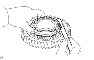
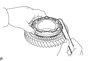
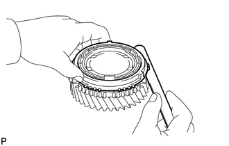
(g) Using a feeler gauge, measure the clearance between the 1st driven gear synchronizer ring set back and the gear spline end. Standard Clearance: 0.98 to 1.82 mm (0.0386 to 0.0717 in.) Minimum Clearance: 0.98 mm (0.0386 in.) If the clearance is below the minimum, replace the 1st driven gear synchronizer ring set. |
|
7. INSPECT 2ND DRIVEN GEAR SYNCHRONIZER RING SET
(a) Coat the 2nd driven gear synchronizer ring set with gear oil.
|
(b) Install the inner ring to the 2nd driven gear. |
|
|
(c) Install the middle ring to the 2nd driven gear. |
|
|
(d) Install the outer ring to the 2nd driven gear. |
|
(e) Coat the 2nd driven gear with gear oil.
|
(f) Check that the 2nd driven gear synchronizer ring set does not turn when the 2nd driven gear synchronizer ring set is pushed to the 2nd driven gear. |
|
|
(g) Using a feeler gauge, measure the clearance between the 2nd driven gear synchronizer ring set back and the gear spline end. Standard Clearance: 1.28 to 2.12 mm (0.0504 to 0.0835 in.) Minimum Clearance: 1.28 mm (0.0504 in.) If the clearance is below the minimum, replace the 2nd driven gear synchronizer ring set. |
|
8. INSPECT 3RD DRIVEN GEAR SYNCHRONIZER RING SET
(a) Coat the 3rd driven gear synchronizer ring set with gear oil.
|
(b) Install the inner ring to the 3rd driven gear. |
|
|
(c) Install the middle ring to the 3rd driven gear. |
|
|
(d) Install the outer ring to the 3rd driven gear. |
|
(e) Coat the 3rd driven gear with gear oil.
|
(f) Check that the 3rd driven gear synchronizer ring set does not turn when the 3rd driven gear synchronizer ring set is pushed to the 3rd driven gear. |
|
|
(g) Using a feeler gauge, measure the clearance between the 3rd driven gear synchronizer ring set back and the gear spline end. Standard Clearance: 1.00 to 2.00 mm (0.0394 to 0.0787 in.) Minimum Clearance: 1.00 mm (0.0394 in.) If the clearance is below the minimum, replace the 3rd driven gear synchronizer ring set. |
|
9. INSPECT 4TH DRIVEN GEAR SYNCHRONIZER RING SET
(a) Coat the 4th driven gear synchronizer ring set with gear oil.
|
(b) Install the inner ring to the 4th driven gear. |
|
|
(c) Install the middle ring to the 4th driven gear. |
|
|
(d) Install the outer ring to the 4th driven gear. |
|
(e) Coat the 4th driven gear with gear oil.
|
(f) Check that the 4th driven gear synchronizer ring set does not turn when the 4th driven gear synchronizer ring set is pushed to the 4th driven gear. |
|
|
(g) Using a feeler gauge, measure the clearance between the 4th driven gear synchronizer ring set back and the gear spline end. Standard Clearance: 0.92 to 1.88 mm (0.0362 to 0.074 in.) Minimum Clearance: 0.92 mm (0.0362 in.) If the clearance is below the minimum, replace the 4th driven gear synchronizer ring set. |
|
10. INSPECT NO. 1 TRANSMISSION HUB SLEEVE
|
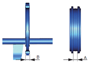
(a) Using a vernier caliper, measure the clearance between the No. 1 transmission hub sleeve and the No. 1 gear shift fork. Standard Clearance (A - B): 0.10 to 0.50 mm (0.00394 to 0.0197 in.) If the clearance is outside the specifications, replace the No. 1 transmission hub sleeve and No. 1 gear shift fork. |
|
11. INSPECT NO. 2 TRANSMISSION HUB SLEEVE
|
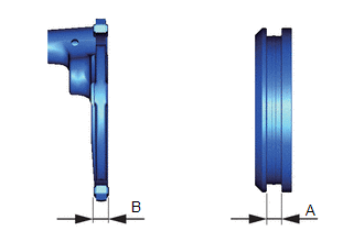
(a) Using a vernier caliper, measure the clearance between the No. 2 transmission hub sleeve and the No. 2 gear shift fork. Standard Clearance (A - B): 0.35 to 0.75 mm (0.0138 to 0.0295 in.) If the clearance is outside the specifications, replace the No. 2 transmission hub sleeve and No. 2 gear shift fork. |
|
12. INSPECT 1ST DRIVEN GEAR THRUST CLEARANCE
|
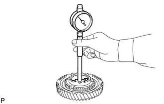
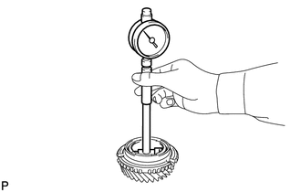
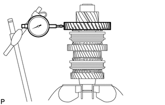
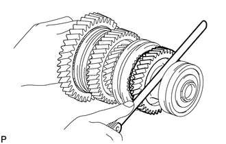
(a) Using a dial indicator, measure the 1st driven gear thrust clearance. Standard Clearance: 0.10 to 0.35 mm (0.00394 to 0.0138 in.) Maximum Clearance: 0.35 mm (0.0138 in.) If the clearance exceeds the maximum, replace the 1st driven gear, needle roller bearing or No. 1 output shaft. |
|
13. INSPECT 1ST DRIVEN GEAR RADIAL CLEARANCE
|
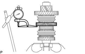
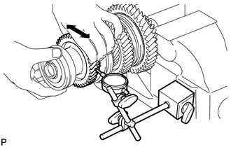
(a) Using a dial indicator, measure the 1st driven gear radial clearance. Standard Clearance: 0.015 to 0.068 mm (0.000591 to 0.00268 in.) Maximum Clearance: 0.068 mm (0.00268 in.) If the clearance exceeds the maximum, replace the 1st driven gear, needle roller bearing or No. 1 output shaft. |
|
14. INSPECT 2ND DRIVEN GEAR THRUST CLEARANCE
|
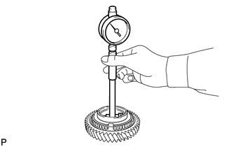
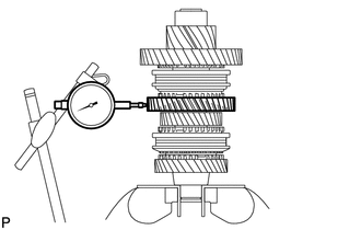
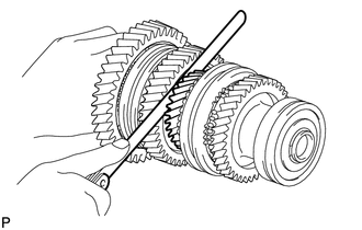
(a) Using a dial indicator, measure the 2nd driven gear thrust clearance. Standard Clearance: 0.11 to 0.46 mm (0.00433 to 0.0181 in.) Maximum Clearance: 0.46 mm (0.0181 in.) If the clearance exceeds the maximum, replace the 2nd driven gear, needle roller bearing or No. 1 output shaft. |
|
15. INSPECT 2ND DRIVEN GEAR RADIAL CLEARANCE
|
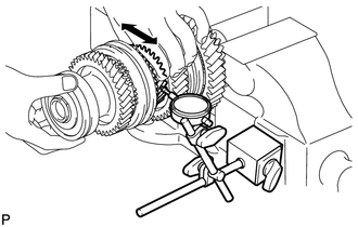
(a) Using a dial indicator, measure the 2nd driven gear radial clearance. Standard Clearance: 0.015 to 0.048 mm (0.000591 to 0.00189 in.) Maximum Clearance: 0.048 mm (0.00189 in.) If the clearance exceeds the maximum, replace the 2nd driven gear, needle roller bearing or No. 1 output shaft. |
|
16. INSPECT 3RD DRIVEN GEAR THRUST CLEARANCE
|
(a) Using a feeler gauge, measure the 3rd driven gear thrust clearance. Standard Clearance: 0.11 to 0.54 mm (0.00433 to 0.0213 in.) Maximum Clearance: 0.54 mm (0.0213 in.) If the clearance exceeds the maximum, replace the 3rd driven gear, needle roller bearing or No. 1 output shaft. |
|
17. INSPECT 3RD DRIVEN GEAR RADIAL CLEARANCE
|
(a) Using a dial indicator, measure the 3rd driven gear radial clearance. Standard Clearance: 0.015 to 0.066 mm (0.000591 to 0.0026 in.) Maximum Clearance: 0.066 mm (0.0026 in.) If the clearance exceeds the maximum, replace the 3rd driven gear, needle roller bearing or No. 1 output shaft. |
|
18. INSPECT 4TH DRIVEN GEAR THRUST CLEARANCE
|
(a) Using a feeler gauge, measure the 4th driven gear thrust clearance. Standard Clearance: 0.10 to 0.65 mm (0.00394 to 0.0256 in.) Maximum Clearance: 0.65 mm (0.0256 in.) If the clearance exceeds the maximum, replace the 4th driven gear, needle roller bearing or No. 1 output shaft. |
|
19. INSPECT 4TH DRIVEN GEAR RADIAL CLEARANCE
|
(a) Using a dial indicator, measure the 4th driven gear radial clearance. Standard Clearance: 0.015 to 0.066 mm (0.000591 to 0.0026 in.) Maximum Clearance: 0.066 mm (0.0026 in.) If the clearance exceeds the maximum, replace the 4th driven gear, needle roller bearing or No. 1 output shaft. |
|
|
|
|